E Production Rx-7 Build

 12-05-09, 10:30 AM
#27
Fabrineer
Thread Starter
Why do the suspension? Costs too much for things that are prone to be heated up and bent straight when you crash the car. I will admit, it would look nice, but this is no show car....
Red is traditional fuel cell color.
Red is traditional fuel cell color.
12-07-09, 12:21 AM
#29
Fabrineer
Thread Starter
It WILL happen, its racing.
The fuel pump came, and the tubing bender and flare for the fuel lines should be here this week. Also, the pipe bender came for the roll cage. I will have lots of pics around christmas time!
The fuel pump came, and the tubing bender and flare for the fuel lines should be here this week. Also, the pipe bender came for the roll cage. I will have lots of pics around christmas time!
12-07-09, 11:48 AM
#30
Urban Explorer

Join Date: May 2009
Location: dexter mi
Posts: 86
Likes: 0
Received 0 Likes
on
0 Posts
dude, gotta stop taking everything I say so literally.
I guess I should have said dont wreck your car and dont kill yourself, then i would have no one to talk about rx7's with.
hopfully your sweet roll cage will protect your cranium, going to share any of the cad pictures?
I guess I should have said dont wreck your car and dont kill yourself, then i would have no one to talk about rx7's with.
hopfully your sweet roll cage will protect your cranium, going to share any of the cad pictures?
12-07-09, 02:04 PM
#31
Fabrineer
Thread Starter
dude, gotta stop taking everything I say so literally.
I guess I should have said dont wreck your car and dont kill yourself, then i would have no one to talk about rx7's with.
hopfully your sweet roll cage will protect your cranium, going to share any of the cad pictures?
I guess I should have said dont wreck your car and dont kill yourself, then i would have no one to talk about rx7's with.
hopfully your sweet roll cage will protect your cranium, going to share any of the cad pictures?
12-07-09, 02:08 PM
#32
Fabrineer
Thread Starter
dude, gotta stop taking everything I say so literally.
I guess I should have said dont wreck your car and dont kill yourself, then i would have no one to talk about rx7's with.
hopfully your sweet roll cage will protect your cranium, going to share any of the cad pictures?
I guess I should have said dont wreck your car and dont kill yourself, then i would have no one to talk about rx7's with.
hopfully your sweet roll cage will protect your cranium, going to share any of the cad pictures?
Should I post the CAD pictures tonight, or should I wait until I get the cage done before I post anything? FEA too?
12-09-09, 09:05 PM
#33
Fabrineer
Thread Starter
Just got some tools in
Well, selling parts off my old setup has helped fund some new goodies: TOOLS!
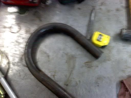
I bought a JD Squared tubing bender for the roll cage (the die was not installed at the point of this picture):
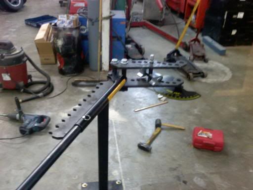
Which put a very nice test bend on this piece (sorry for the crappy photo - cell phone):
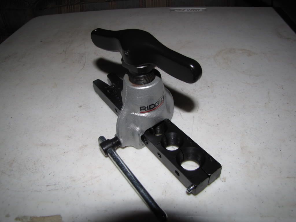
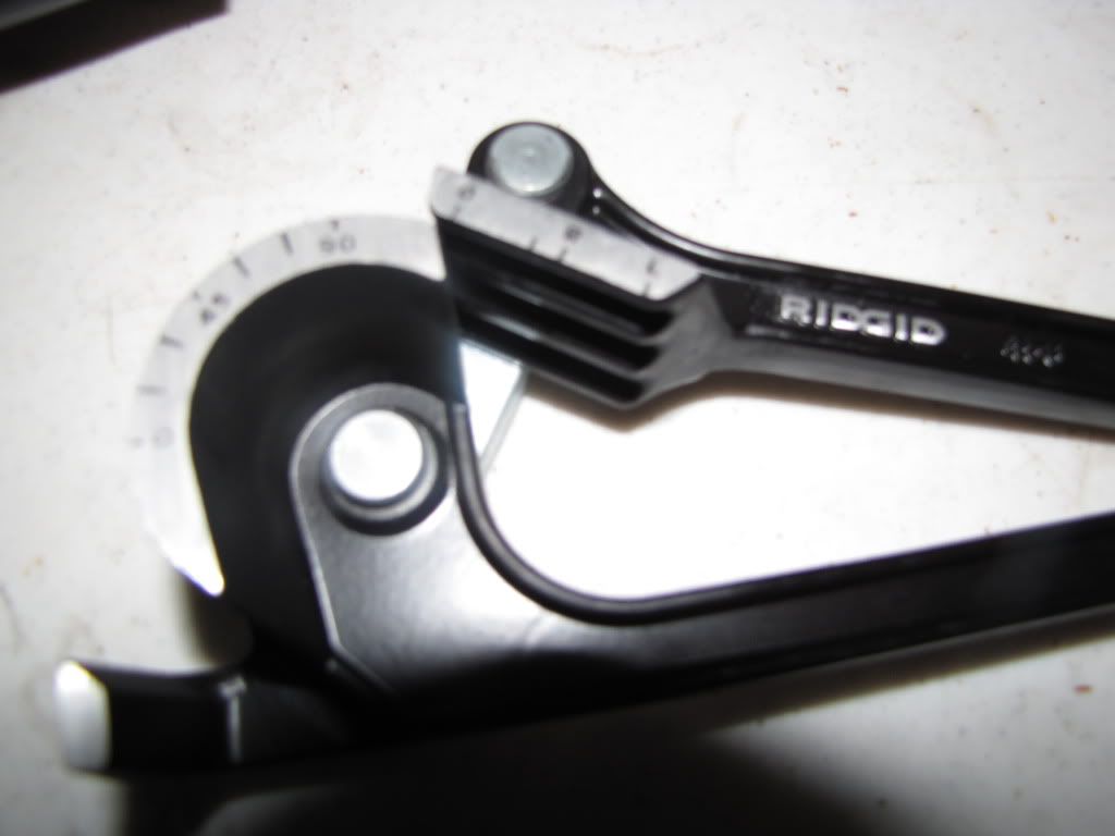
And I bought a few Rigid tools for the fuel lines and oil lines on the engine. You wouldn't believe how much cheaper and lighter it is to run 6061 aluminum hard line, even after the purchase of a $100 flare tool and $100 bender. The nuts that bolt the flare to the male AN fitting are like $2-$3 each, plus $2 for a sleeve. Instead of $25-$50 for each hose end.
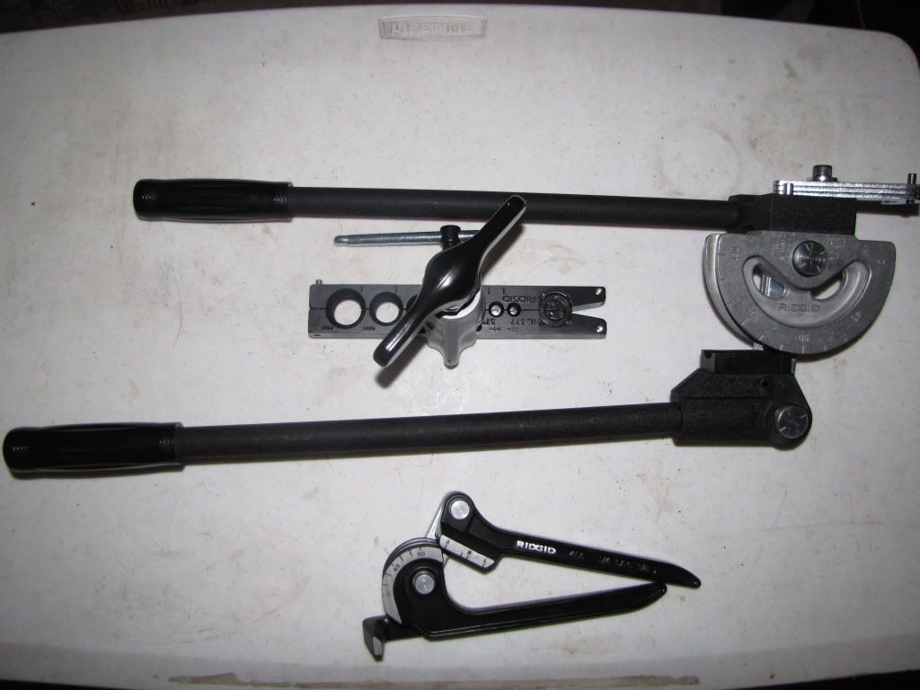
SAE 37 degree flare tool. This works for JIC fittings (AN - Army Navy fittings is JIC) from 1/4" OD to 3/4" OD tubing/hose (that's 4/16" or -04 and 12/16" or -12 for the AN guys):
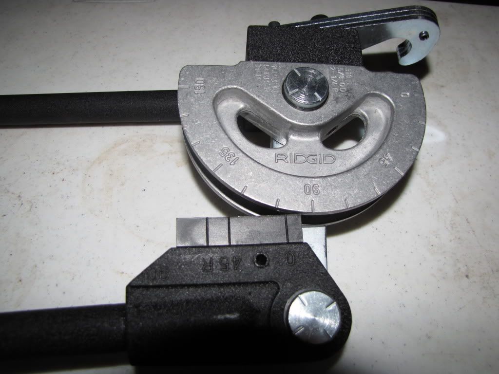
Rigid Tri bender this thing was only $35 - parts of it are made in china >:-( BUT, it will get the job done just fine. It handes 1/4", 5/16", and 3/8" (-04, -05, -06)
And last but not least, the behemoth of a bender, the Rigid bender for 5/8" OD (AN -10) tubing. This thing will handle stainless, mild steel, copper, and aluminum tubing of various thicknesses. Its like 2 feet long and 15 pounds with a 2.25" CLR, which is sort of large, but it gives the flexibility of putting multiple bends in a small area. I'll be using this for my oil lines on the engine and possibly to and from the oil cooler (with a flexible line from the engine to the chassis, of course).
I bought a JD Squared tubing bender for the roll cage (the die was not installed at the point of this picture):
Which put a very nice test bend on this piece (sorry for the crappy photo - cell phone):
And I bought a few Rigid tools for the fuel lines and oil lines on the engine. You wouldn't believe how much cheaper and lighter it is to run 6061 aluminum hard line, even after the purchase of a $100 flare tool and $100 bender. The nuts that bolt the flare to the male AN fitting are like $2-$3 each, plus $2 for a sleeve. Instead of $25-$50 for each hose end.
SAE 37 degree flare tool. This works for JIC fittings (AN - Army Navy fittings is JIC) from 1/4" OD to 3/4" OD tubing/hose (that's 4/16" or -04 and 12/16" or -12 for the AN guys):
Rigid Tri bender this thing was only $35 - parts of it are made in china >:-( BUT, it will get the job done just fine. It handes 1/4", 5/16", and 3/8" (-04, -05, -06)
And last but not least, the behemoth of a bender, the Rigid bender for 5/8" OD (AN -10) tubing. This thing will handle stainless, mild steel, copper, and aluminum tubing of various thicknesses. Its like 2 feet long and 15 pounds with a 2.25" CLR, which is sort of large, but it gives the flexibility of putting multiple bends in a small area. I'll be using this for my oil lines on the engine and possibly to and from the oil cooler (with a flexible line from the engine to the chassis, of course).
 12-09-09, 10:12 PM
#35
Fabrineer
Thread Starter
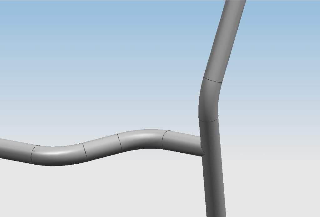
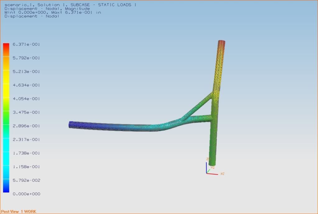
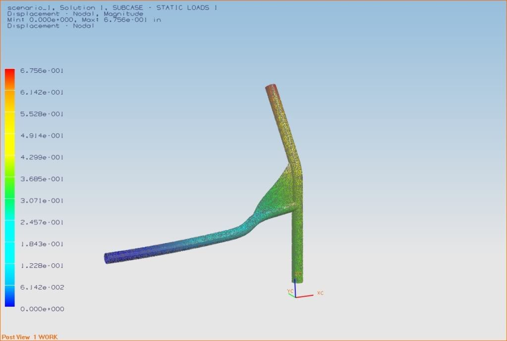
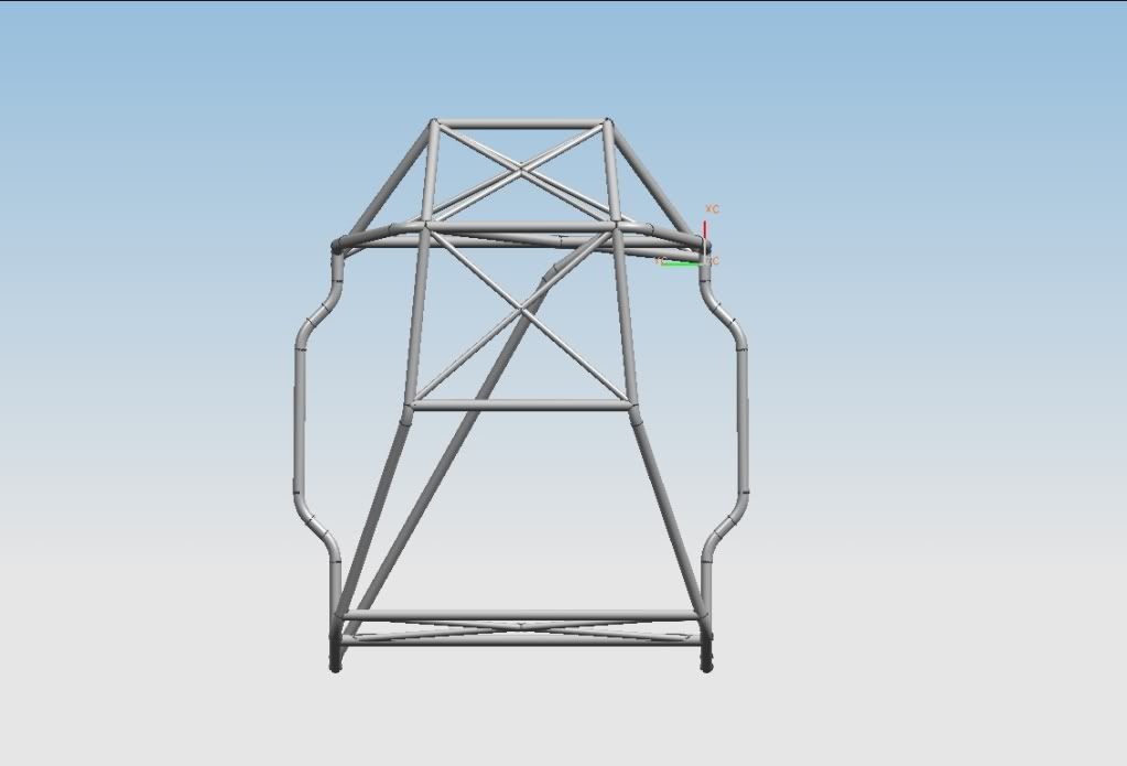
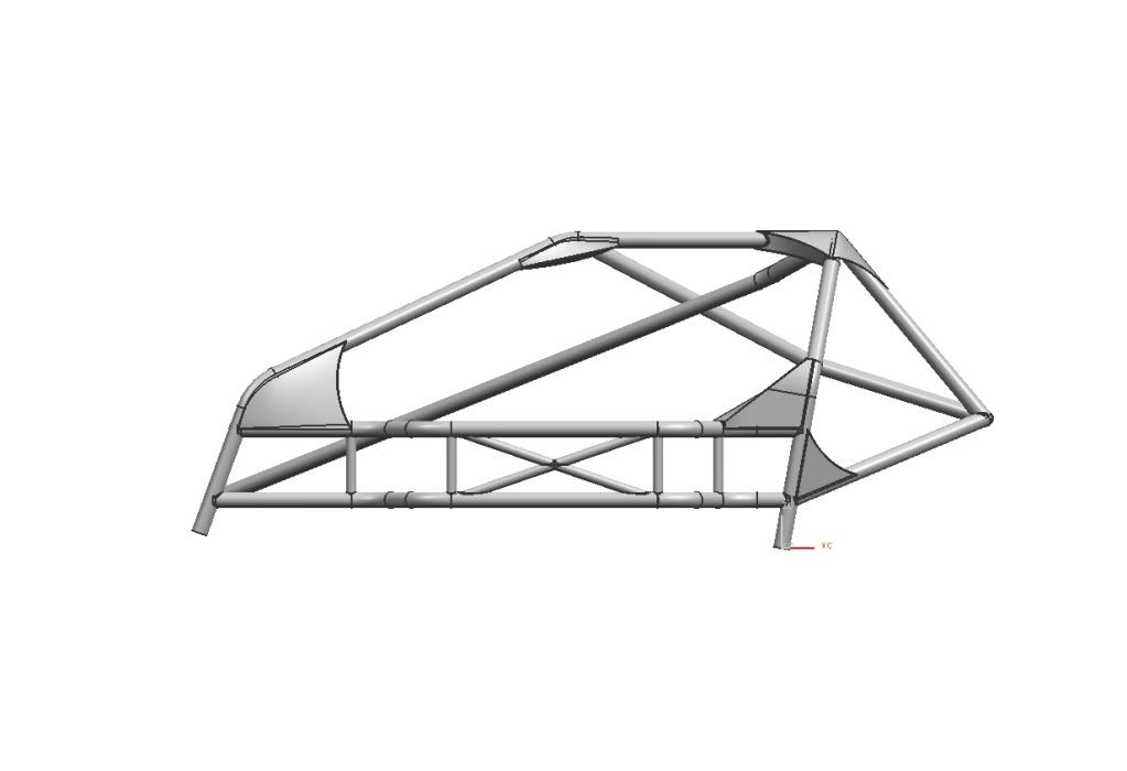
Roll Cage Preliminary Design: CAD and FEA
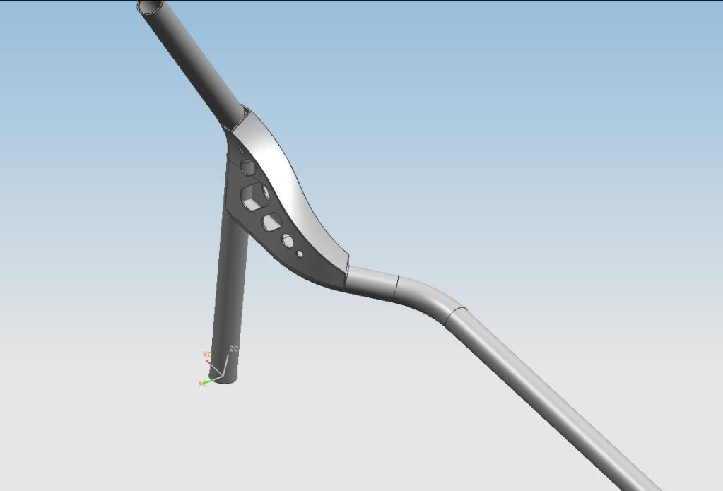
In my quest for light weight, low center of gravity, and high torsional rigidity, I spent some time on roll cage design. I took some rough measurements of the stripped interior of the vehicle, located some good mounting points, and started designing.
I used Unigraphics NX to design the cage. The main purpose of the CAD work was to visualize the structure, then set up a geometry in which I could FEA (Finite Element Analysis) to further analyze high stress and high deflection areas of the structure.
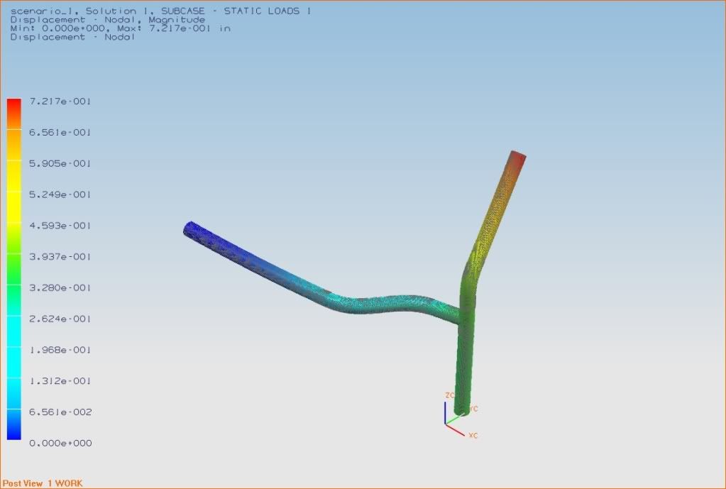
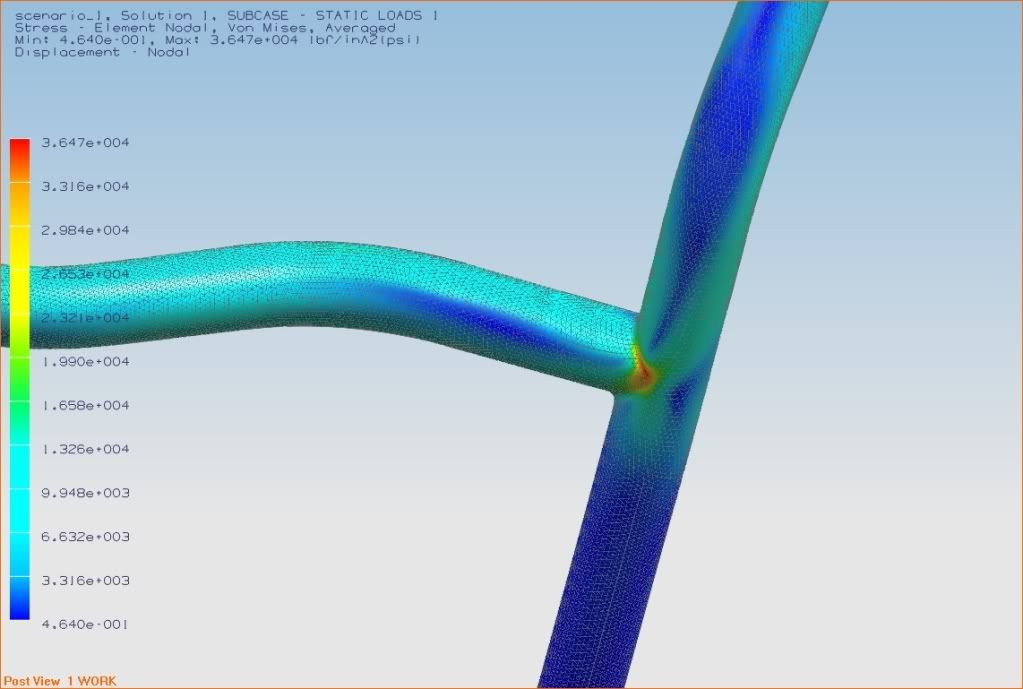
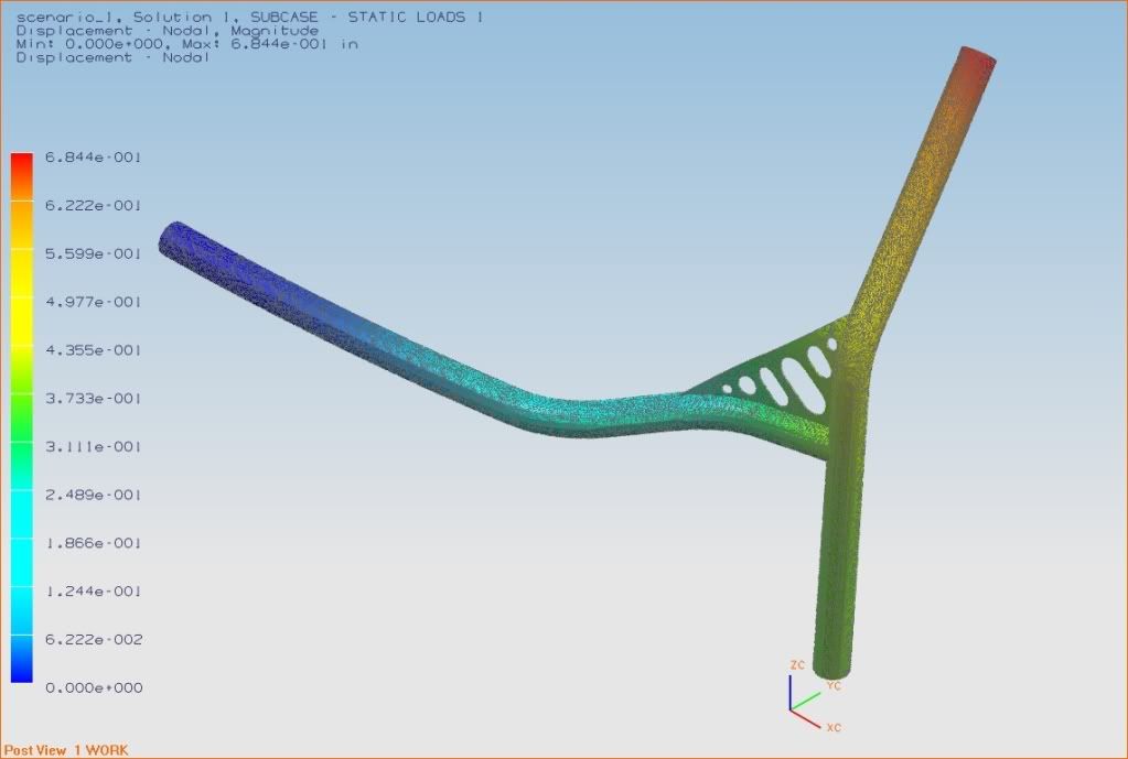
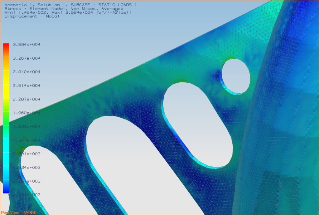
One of the highest stress areas of a cage, under normal racing operation (what I call racing forces), are joints. This is an area where forces must turn a sharp angle and transmit themselves along (possibly) poor moments of inertia, such as the base of a cantilevered beam, or simply a 90 degree joint. This creates stress risers and raises deflection. To counteract this effect, one applies gussets.
To simplify analysis and engineering time, I did the finite element analysis on a selected 90 degree joint in the structuer and studied the differences between various gusset designs to find the best comprimise of weight vs. stiffness.
Unigraphics NX will can calculate the volume of material used; and hence, a mass. And if you know the exact density of the material, a weight.
The following pictures depict my design and analysis of the roll cage structure. The design is not complete. I have picked up a paper illustrating the energy absorbing characteristics of tubular structures, which I plan to incorporate into my design to make not only an ultra stiff and ultra lightweight structure, but also an ultra safe structure (think 1959 Chevy Bel Aire compared to Chevrolet Malibu - they achieved all 3). Thanks to NATEFRAME for locating and printing the article for me!
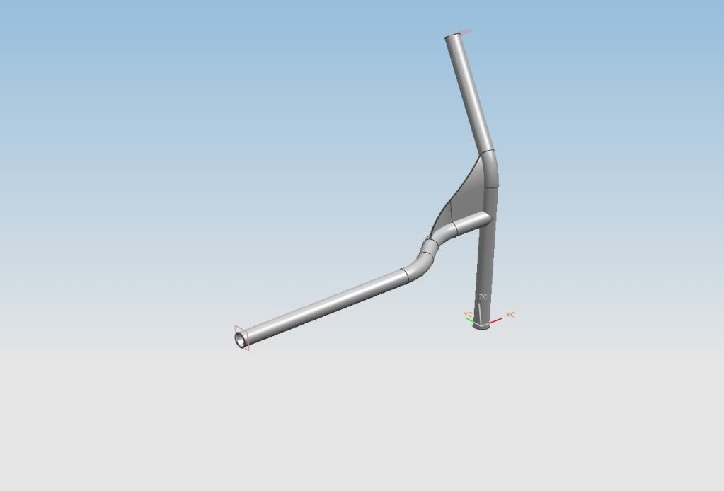
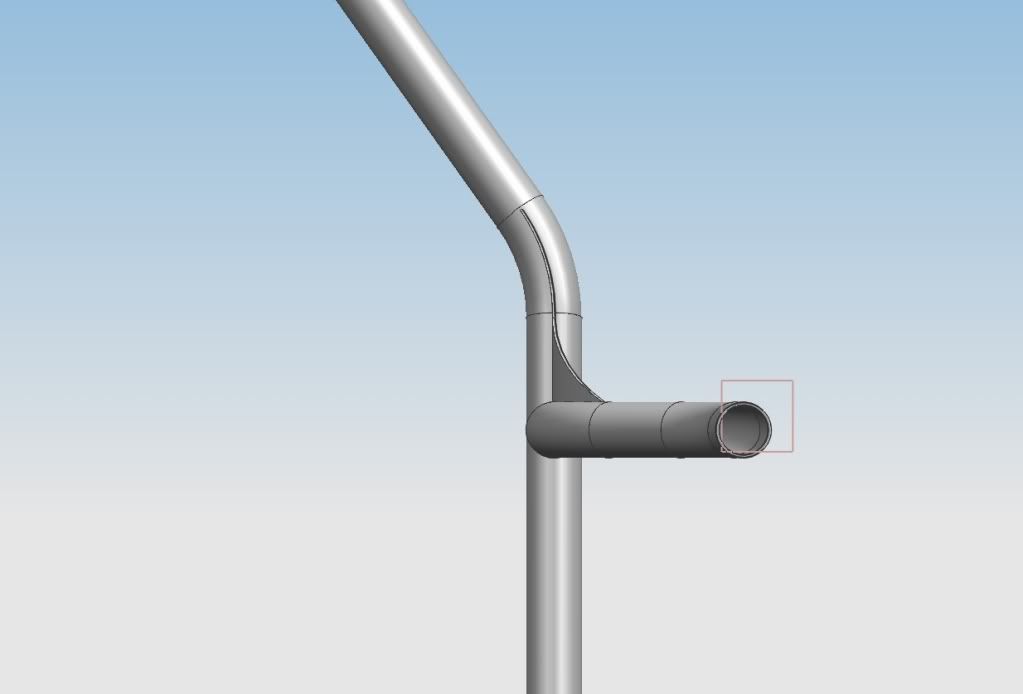
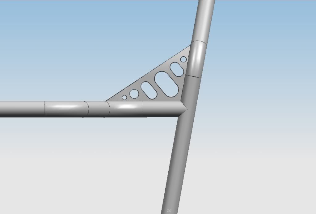
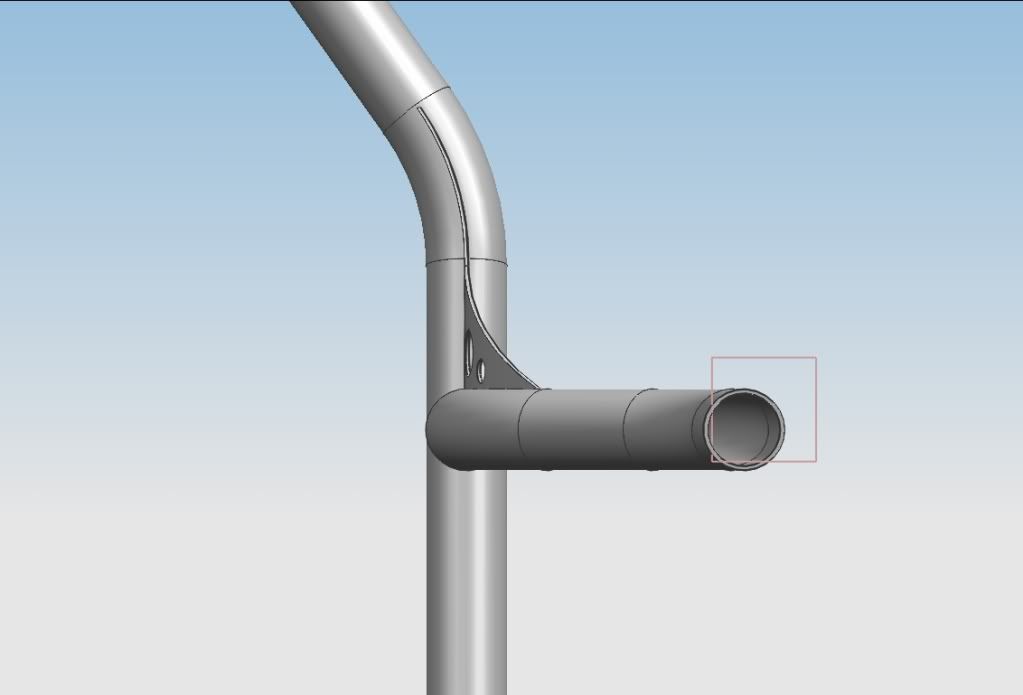
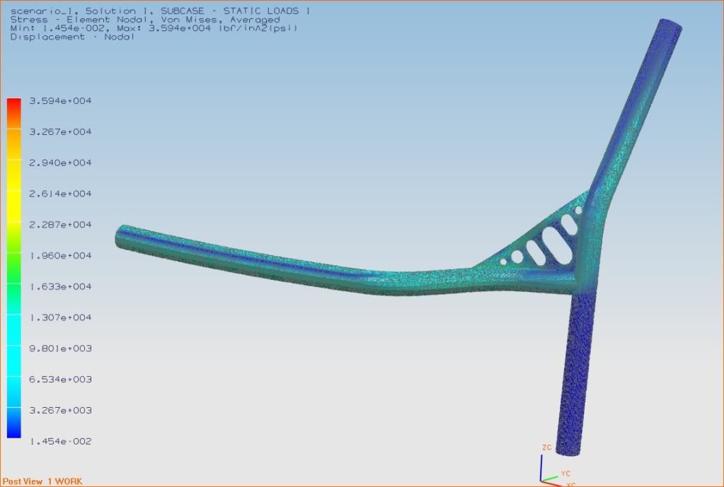
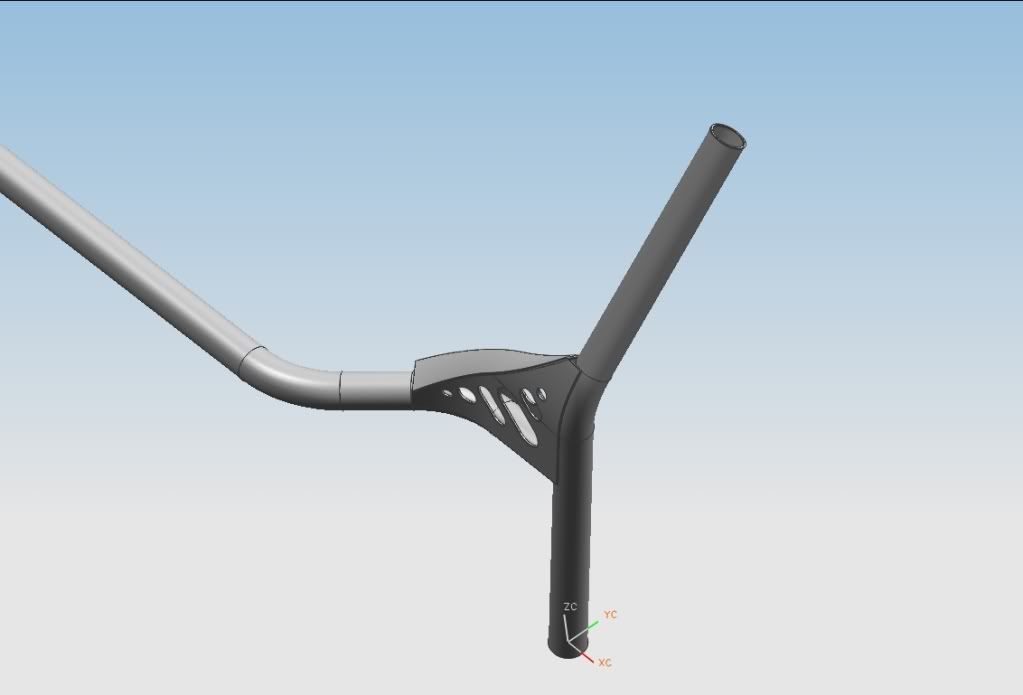
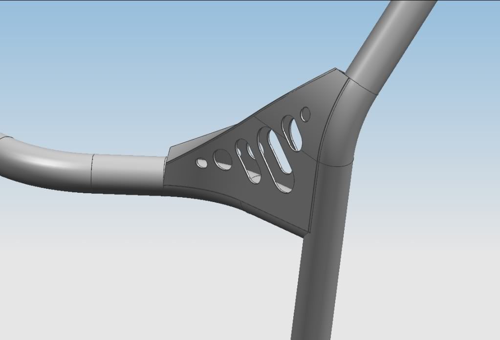
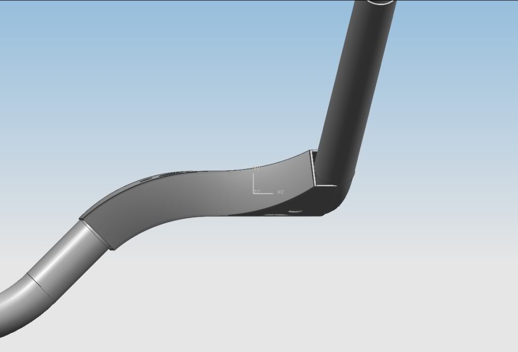
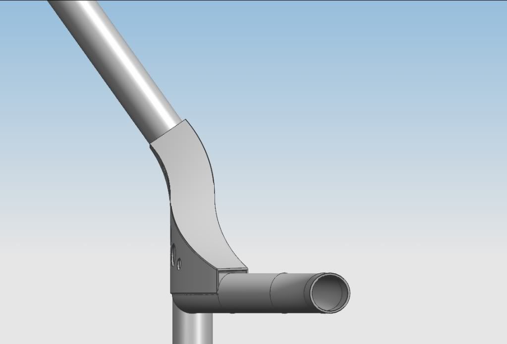
CAD and FEA of Gusset Designs, and comparison to a joint with no gusset:
Joint with no gusset
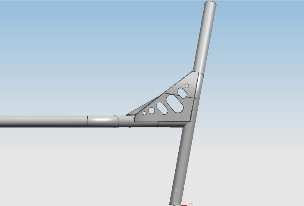
Joint with tubular gusset - the common roll cage design. The 2nd heaviest and the 2nd most stiff (not by much)
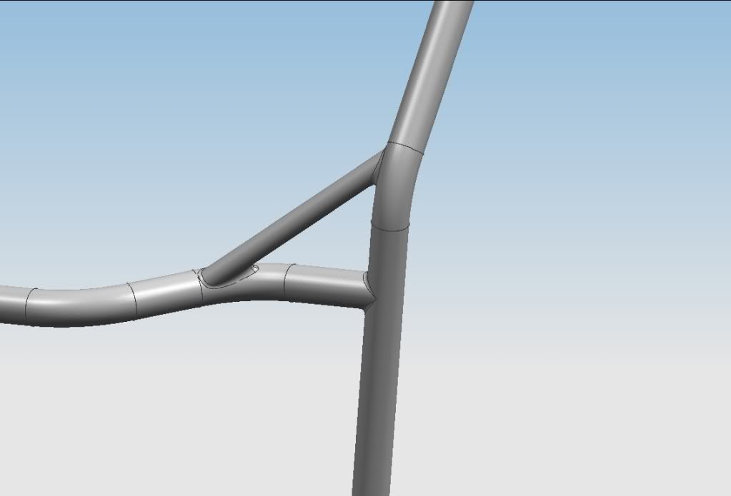
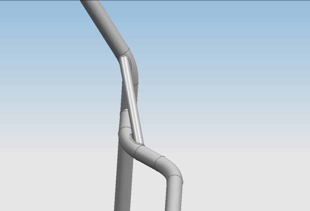
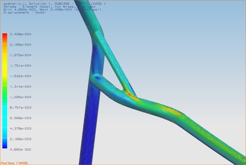
Joint with plate gusset:
I used Unigraphics NX to design the cage. The main purpose of the CAD work was to visualize the structure, then set up a geometry in which I could FEA (Finite Element Analysis) to further analyze high stress and high deflection areas of the structure.
One of the highest stress areas of a cage, under normal racing operation (what I call racing forces), are joints. This is an area where forces must turn a sharp angle and transmit themselves along (possibly) poor moments of inertia, such as the base of a cantilevered beam, or simply a 90 degree joint. This creates stress risers and raises deflection. To counteract this effect, one applies gussets.
To simplify analysis and engineering time, I did the finite element analysis on a selected 90 degree joint in the structuer and studied the differences between various gusset designs to find the best comprimise of weight vs. stiffness.
Unigraphics NX will can calculate the volume of material used; and hence, a mass. And if you know the exact density of the material, a weight.
The following pictures depict my design and analysis of the roll cage structure. The design is not complete. I have picked up a paper illustrating the energy absorbing characteristics of tubular structures, which I plan to incorporate into my design to make not only an ultra stiff and ultra lightweight structure, but also an ultra safe structure (think 1959 Chevy Bel Aire compared to Chevrolet Malibu - they achieved all 3). Thanks to NATEFRAME for locating and printing the article for me!
CAD and FEA of Gusset Designs, and comparison to a joint with no gusset:
Joint with no gusset
Joint with tubular gusset - the common roll cage design. The 2nd heaviest and the 2nd most stiff (not by much)
Joint with plate gusset:
 12-09-09, 10:14 PM
#37
Fabrineer
Thread Starter
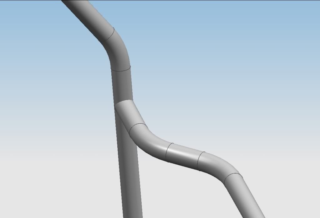
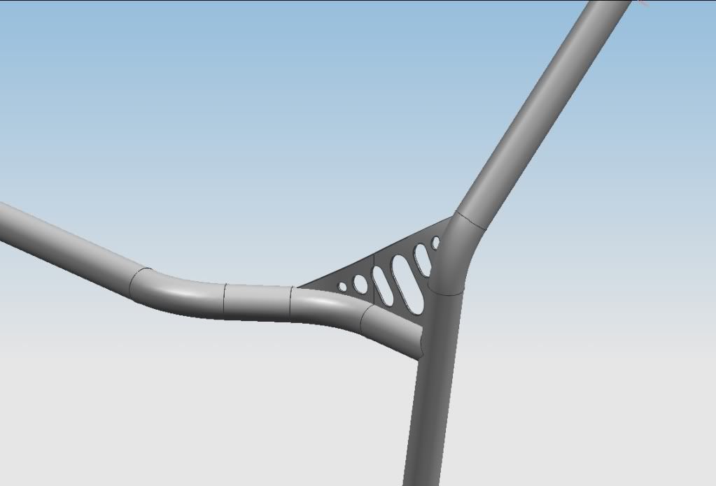
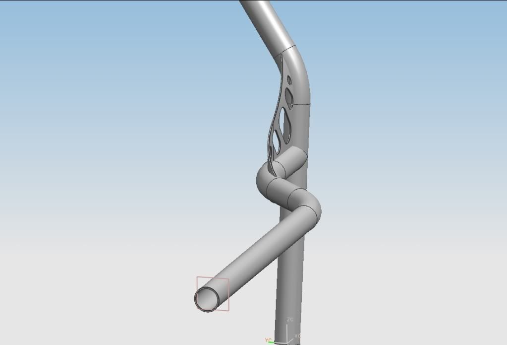
More Roll Cage CAD and FEA
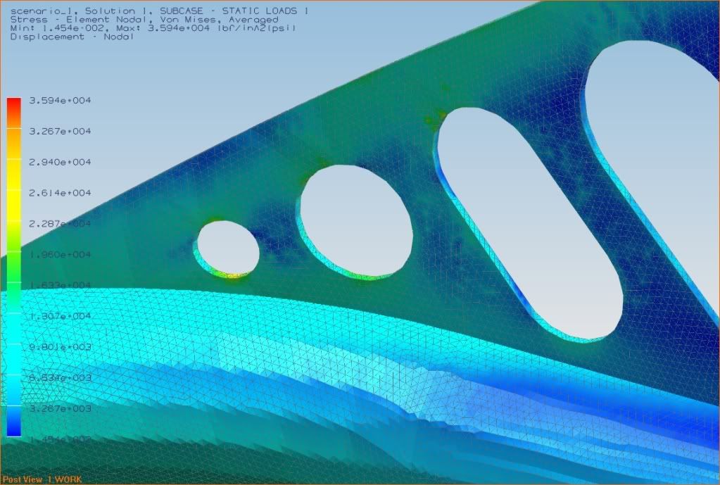
Joint with dual plate gussets - slotted (Heavies - not by much. And stiffest - by a fair margin)
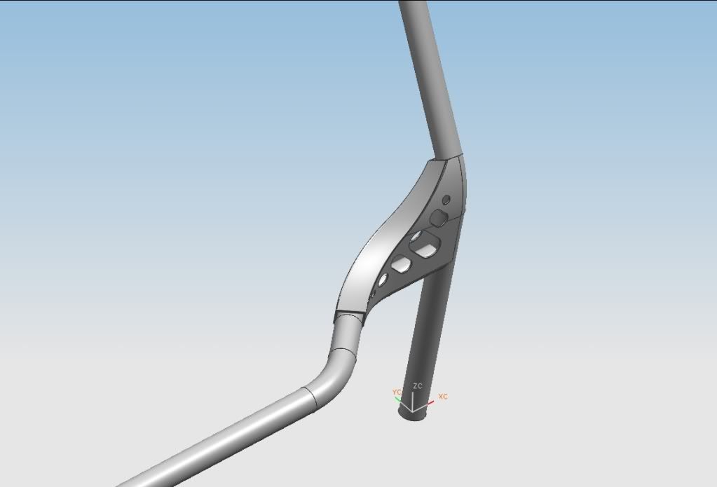
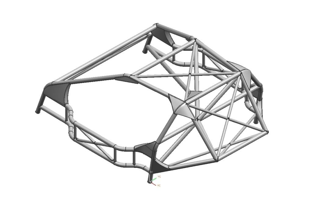
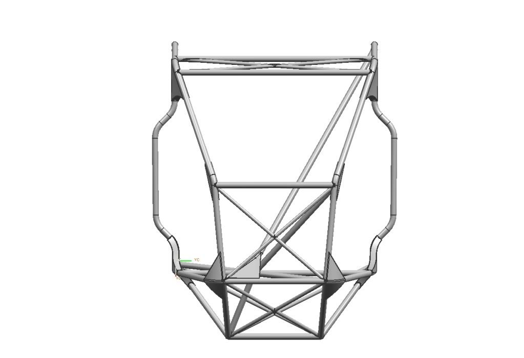
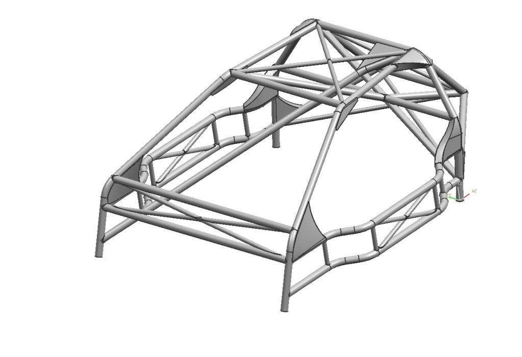
Preliminary roll cage design:
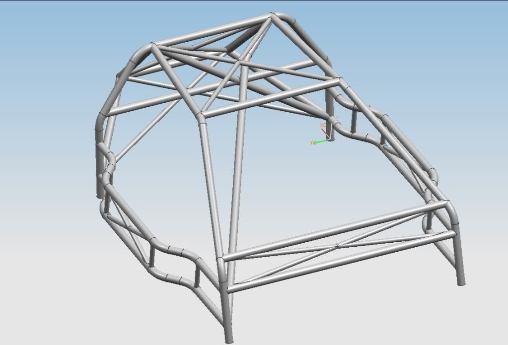
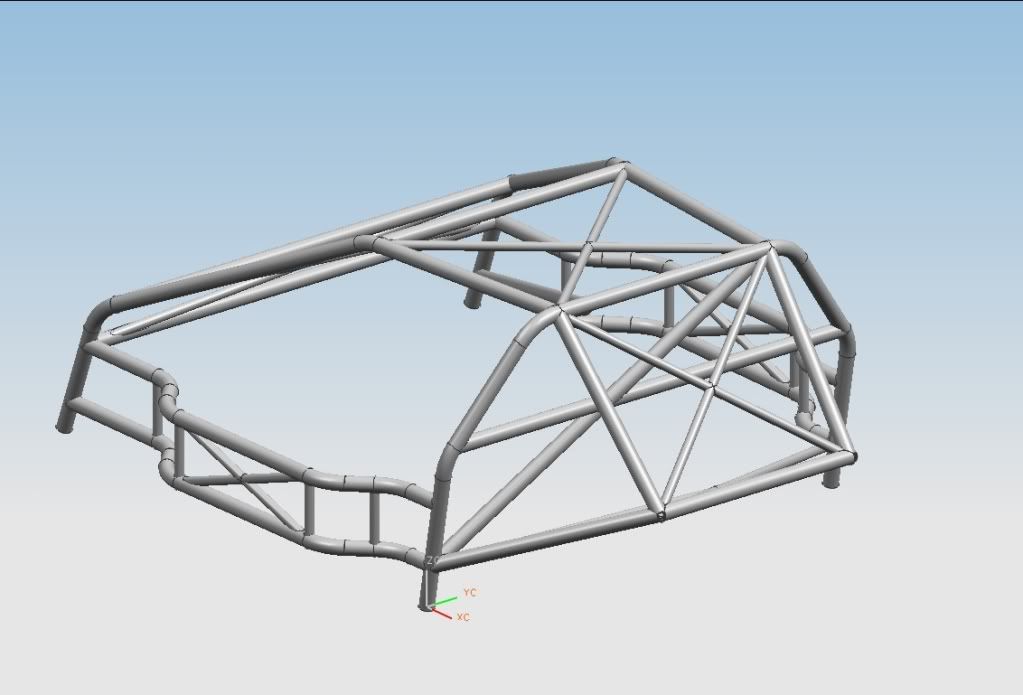
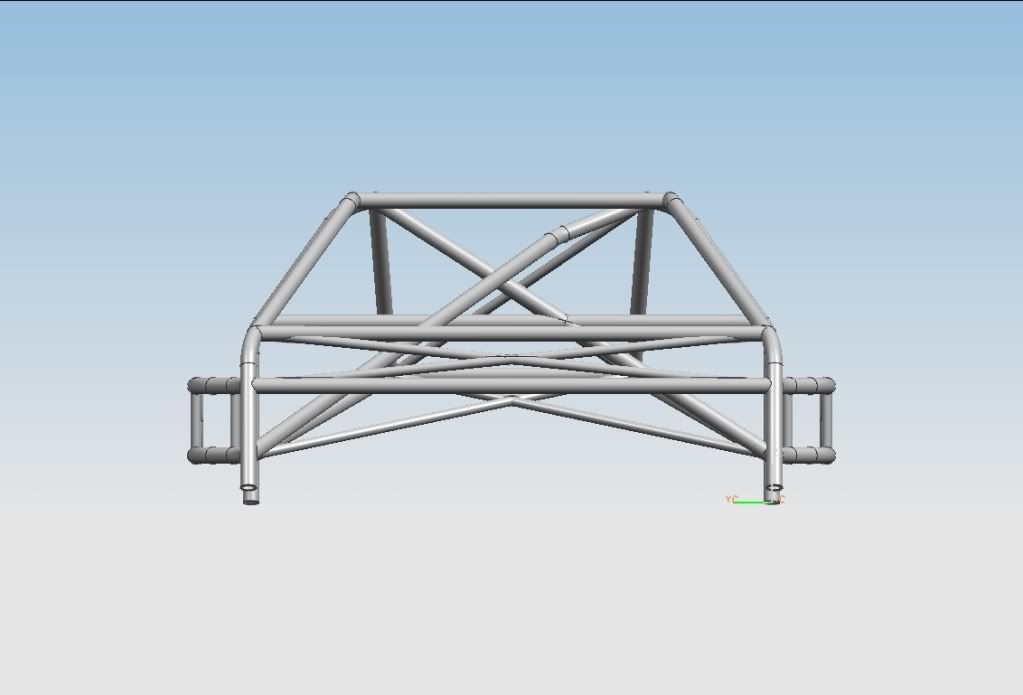
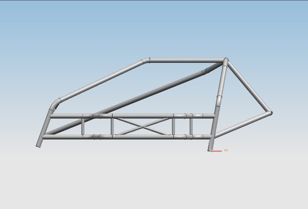
Preliminary roll cage design:
 12-10-09, 03:36 PM
#40
How tall are you? You may want to bow the "harness" bar to allow for more room there. Other than that, looks nice. The stress analysis is interesting. Make sure to consider what you're running through the firewall to triangulate the front end and how it fits with the rest of the design.
12-10-09, 07:36 PM
#41
Fabrineer
Thread Starter
How tall are you? You may want to bow the "harness" bar to allow for more room there. Other than that, looks nice. The stress analysis is interesting. Make sure to consider what you're running through the firewall to triangulate the front end and how it fits with the rest of the design.
Also, I haven't had time to measure the dimensions through the firewall. The analysis on the entire cage won't happen until the basic structure is finished. I am trying to optimize gusset location, thicknesses, and dimensions. If I had an entire CAD model of the car, this would be a lot easier!
12-15-09, 11:26 AM
#43
Fabrineer
Thread Starter
Final exams have been crazy. I'll be starting back on this project tomorrow. I'll be plumbing the fuel system and starting on the roll cage; but I have a dilemma - I am not sure how I'm going to get the base plates for the roll cage cut since I don't have a bandsaw.
Cheers.
Cheers.
12-16-09, 06:32 PM
#44
You can save weight and time and make a stronger cage if you skip the NASCAR door bars on the passenger side.
FEA is fun to play with but remember you have a car attached to this cage. There is a lot of extra weight in the form of overkill in your design. The chassis really only needs to be about 4 times stiffer than your suspension is capable of loading it. The focus should be on drivers side crush protection(move your seat over to the tunnel) and top of the windshield. The top of the windshield is where every sedan takes the hardest hit if it goes over.
Here is mine in the cage thread, posts 319 and 323.
https://www.rx7club.com/race-car-tech-103/show-pics-your-cages-please-395960/page13/
12-16-09, 07:44 PM
#45
Fabrineer
Thread Starter
You can save weight and time and make a stronger cage if you skip the NASCAR door bars on the passenger side.
FEA is fun to play with but remember you have a car attached to this cage. There is a lot of extra weight in the form of overkill in your design. The chassis really only needs to be about 4 times stiffer than your suspension is capable of loading it. The focus should be on drivers side crush protection(move your seat over to the tunnel) and top of the windshield. The top of the windshield is where every sedan takes the hardest hit if it goes over.
Here is mine in the cage thread, posts 319 and 323.
https://www.rx7club.com/showthread.php?t=395960&page=13
The extra x-bracing bars are 1"OD x 0.049 wall...
By the way, nice looking cage, I may have to use some features from your cage for ideas on my design, weight permitting. It seems as though my cage is most lacking the roll over protection.
12-16-09, 08:25 PM
#46
Fabrineer
Thread Starter
Also, I especially like your use of the passenger compartment for increasing lateral and torsional rigidity.
However, I'm not quite sure what you mean by "the chassis really only needs to be about 4 times stiffer than your suspension is capable of loading it." Do you mean that the chassis should yield at 4 times the load of the maximum lateral g's encountered in cornering? Or should it fail at 4 times that load? Or is it either one of those but instead of just lateral g's, is it the combined loading of spring forces and lateral g's?
Stiffness (more properly, the modulus of elasticity) is the stress (force/area) vs. the strain (% deflection). The steeper the slope on the stress-strain curve, the stiffer the material. It makes no statement about the factor of safety regarding yielding or failure.
You can see why I'm in a quandary over your statement.
12-16-09, 08:53 PM
#47
Your looking for resistance to the twisting of the chassis. A full tube frame chassis will come in around 12,000lbs/degree, I've seen them come in at over 14K/degree but you would never be able to tell the difference on the track.
With FEA you would pin down the back using the spring perches and put a load on the front spring perches to twist. Its been about 16 years since I played with UAI NASTRAN( I think its MSC NASTRAN now?) I would have to dust off the nodes and elements department in my brain to converse at your 'final exams-crammed skull' level.
With FEA you would pin down the back using the spring perches and put a load on the front spring perches to twist. Its been about 16 years since I played with UAI NASTRAN( I think its MSC NASTRAN now?) I would have to dust off the nodes and elements department in my brain to converse at your 'final exams-crammed skull' level.
12-16-09, 09:52 PM
#48
Fabrineer
Thread Starter
Yes, it iss MSC Nastran now, but there are other ones that are just as good, such as ABAQUS. I am using unigraphics integrated solver, structures PE, which works fine for linear statics solutions. I am not looking at yielding, over-loading failure, or fatigue failure.
My design goal is to have the maximum stiffness for the minimum weight. If there is a marginal, say 5% loss in stiffness for a 3% loss in weight, I would apt for the lower weight, as the car is light, and as you say, you may not even notice it on the track.
I will most likeley incorporate some features of your design. I had a smiliar idea for the tubes passing through the firewall, but I didn't model them. Also, I had the same idea, but didn't model it, for the diagonal bar that goes from the right front corner of the cage back to the left rear shock tower.
The thing I tried to keep in mind is that lateral forces in the rear are passed through the subframe, not the shock top, so I am attempting to use that as the point to stiffen for torsional rigidity. I may lighten up my rear "strut tower" for this reason.
12-16-09, 10:17 PM
#49
Fabrineer
Thread Starter
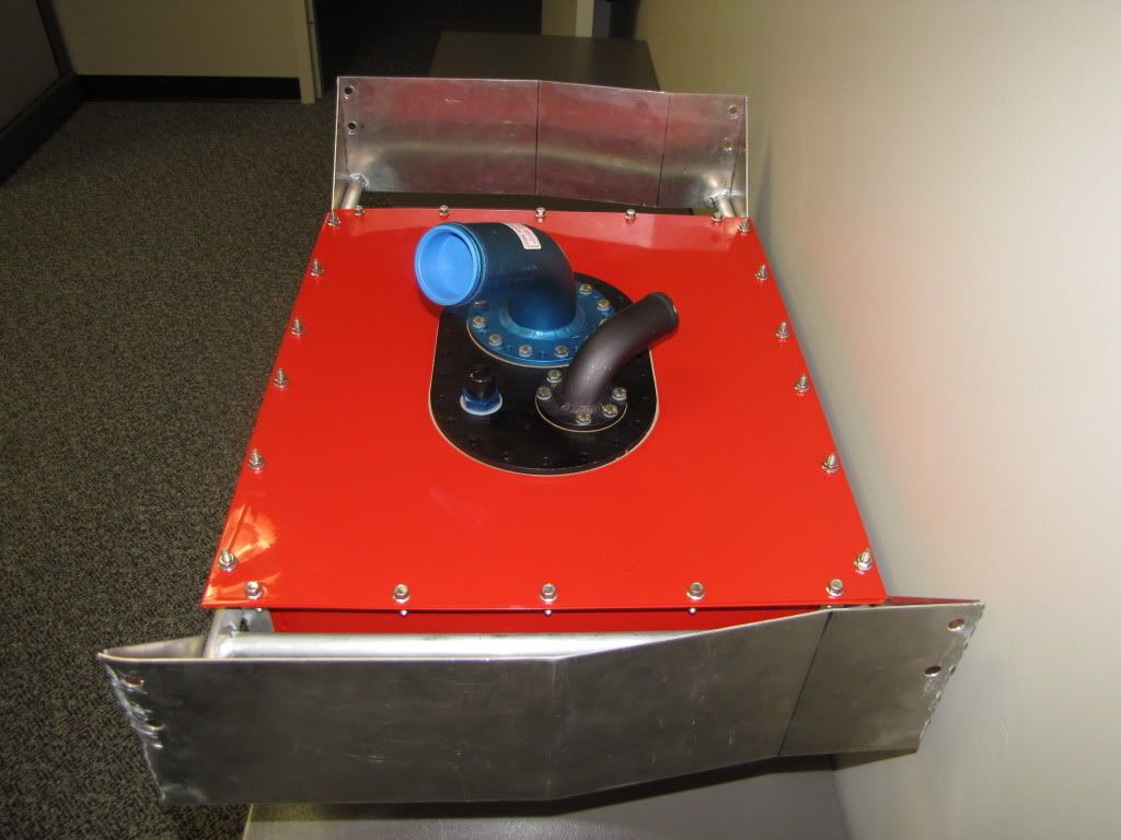
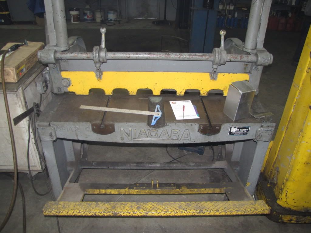
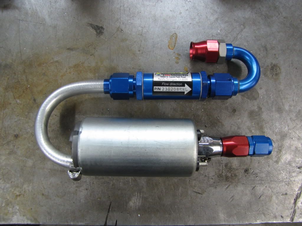
Surge Tank
Niagara Foot Shear
One of my new tools in my arsenal. This thing makes life much easier. Its probably older than my age*3...
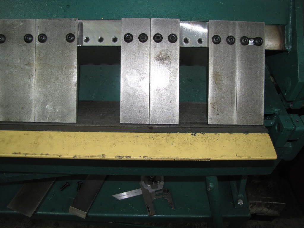
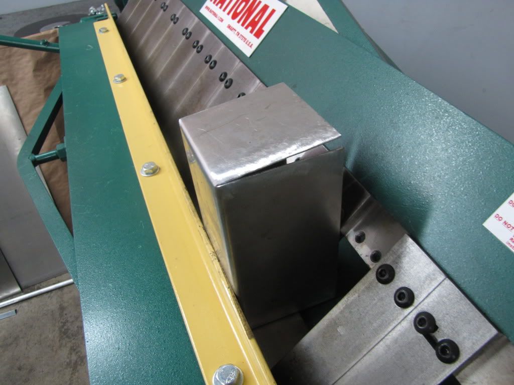
National Box and Pan Hand Break
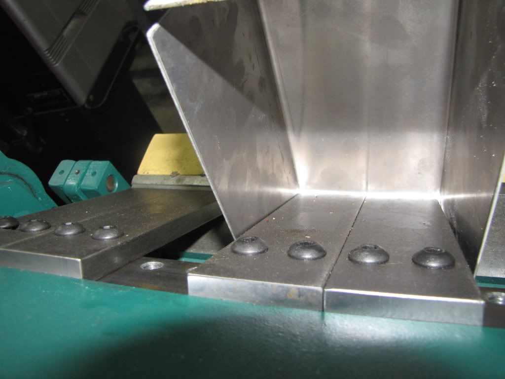
Another new tool in my arsenal. Again, makes life easier. Here's the setup I had to use to make a box:
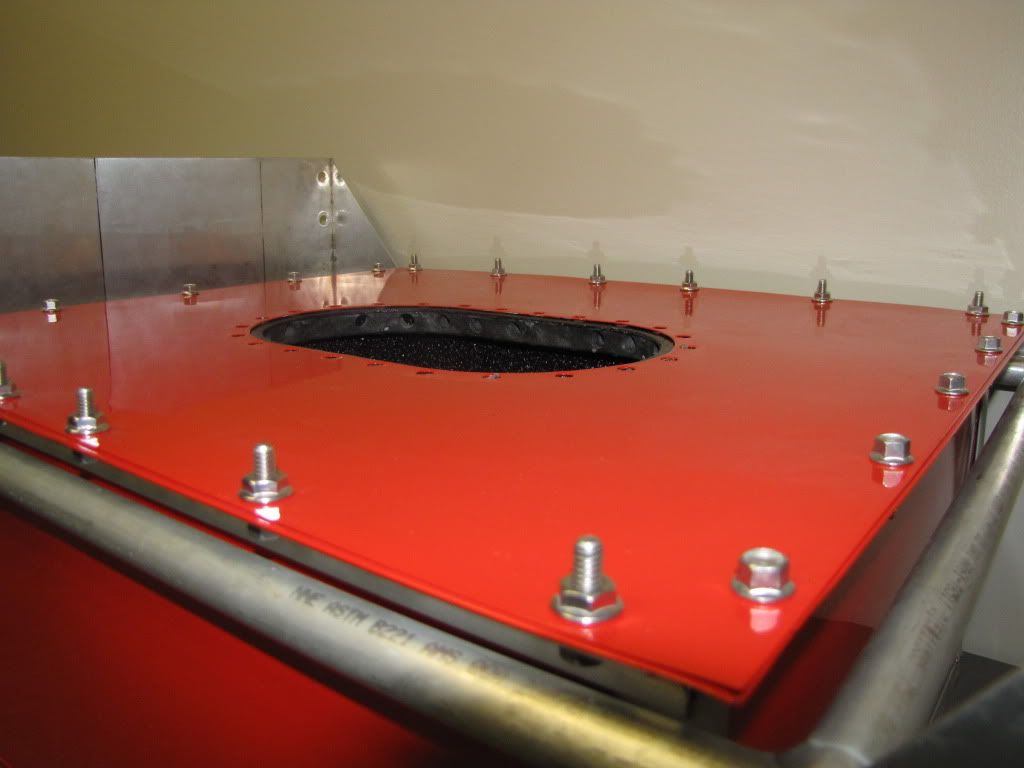
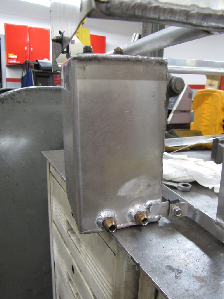
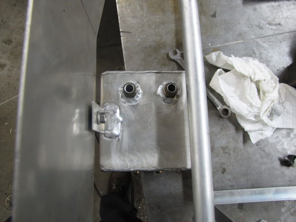
Surge Tank Fabrication
Breaking the plate into a box:
Tack welded together
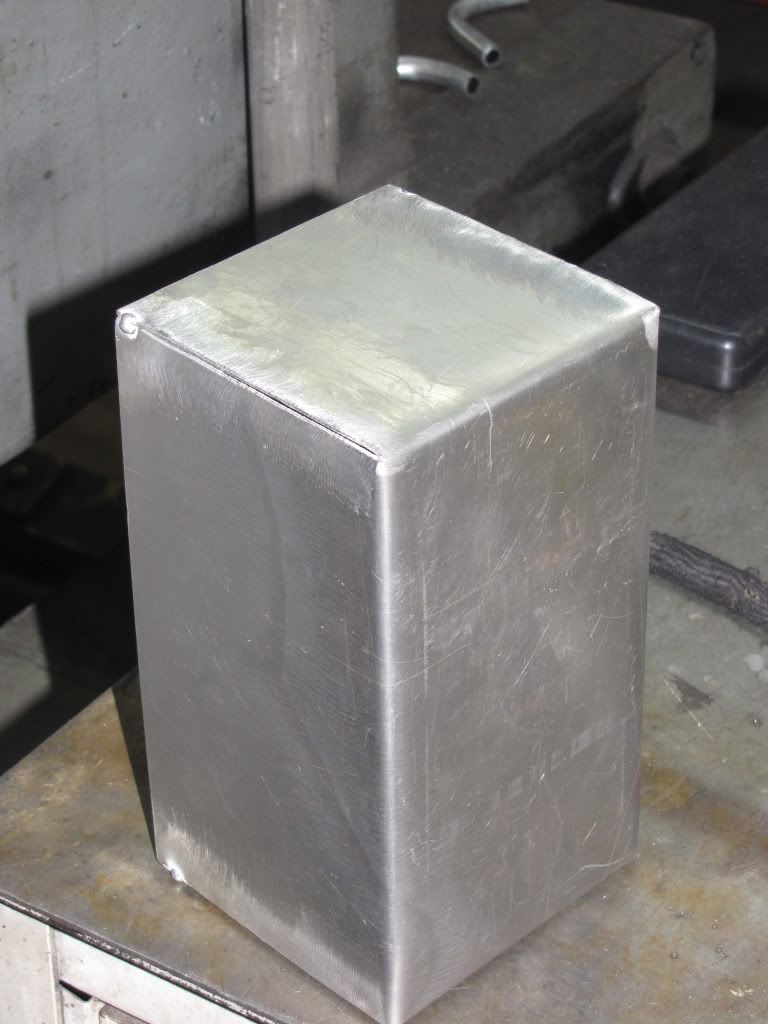
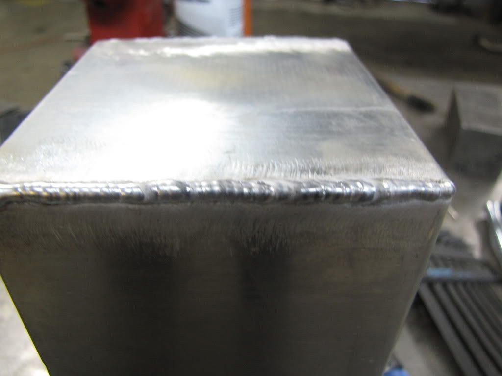
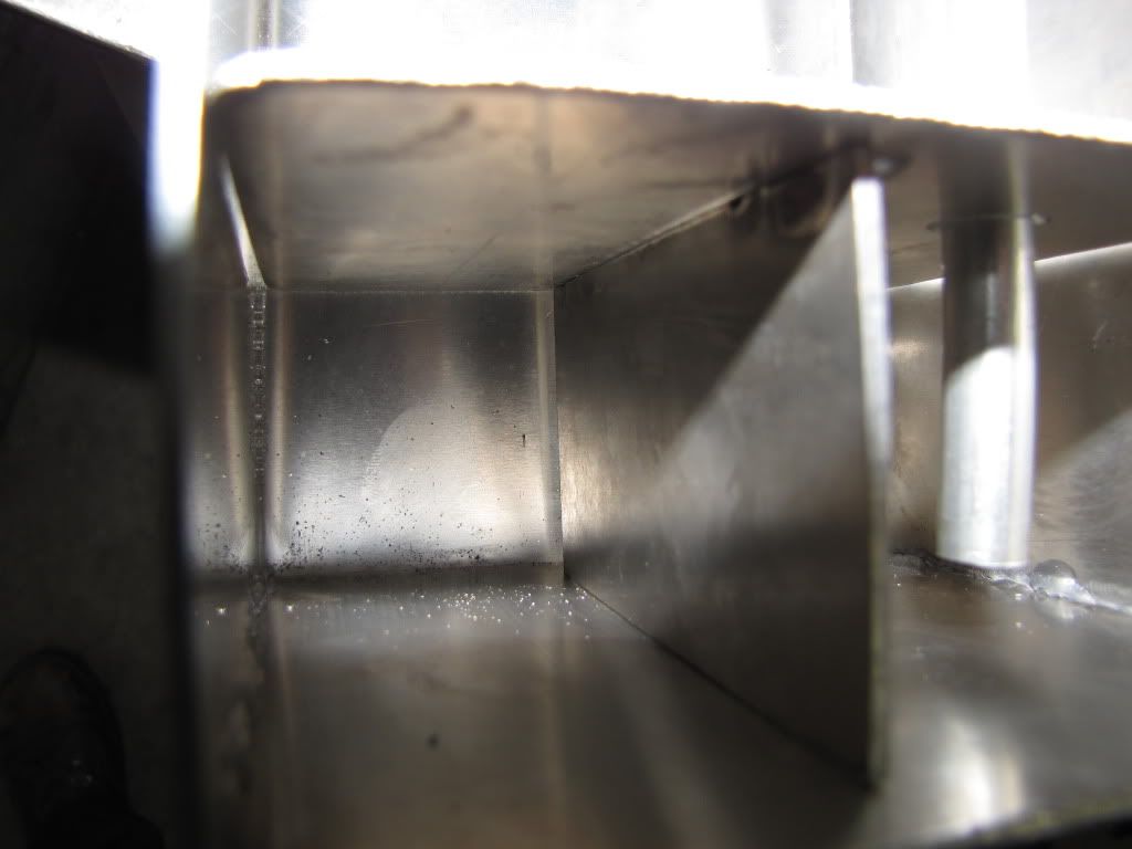
Welded the seam. This one was OK. I went back over the welds without filler rod to ensure that it didn't leak. Normally, I wouldn't do this, but its fuel, and it could be under pressure if there's a failure in the fuel system (nominally, its not under any pressure).
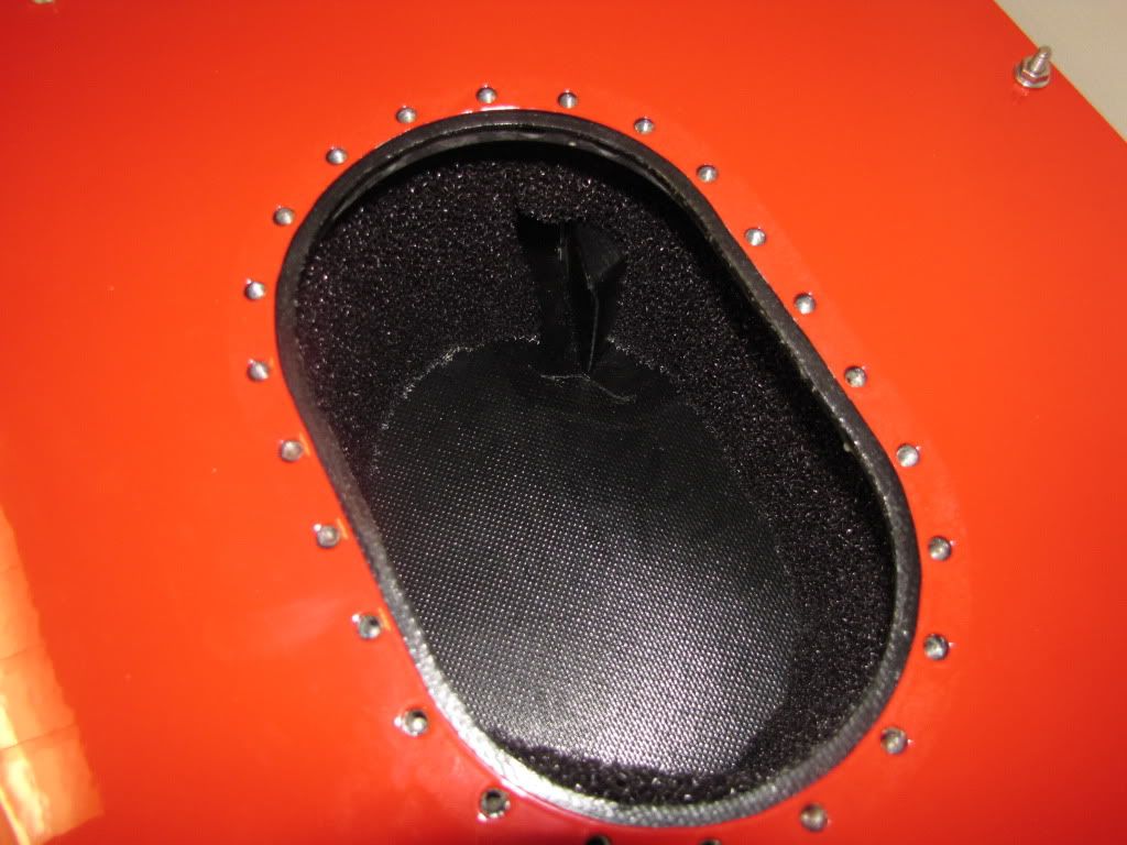
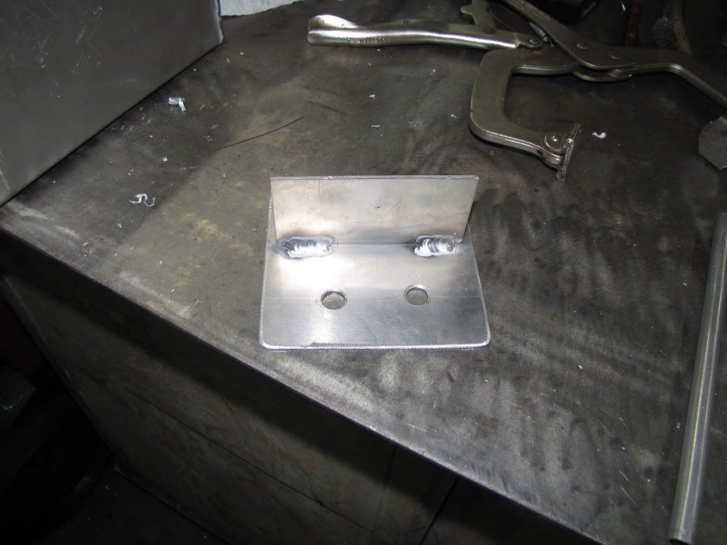
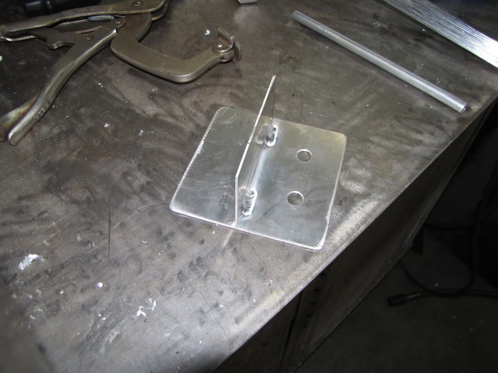
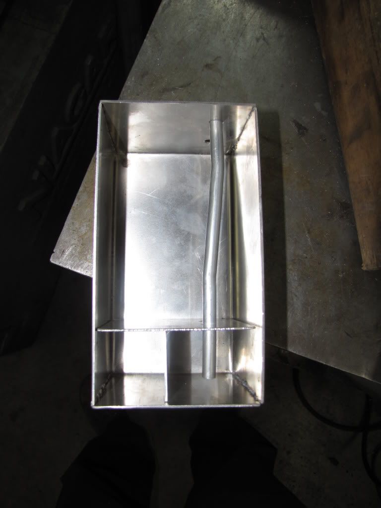
Fabricating the baffle inside. I wanted to make sure there was no possible way for the engine to be starved of fuel, even if the tank was low and I was mid corner, then powering out.
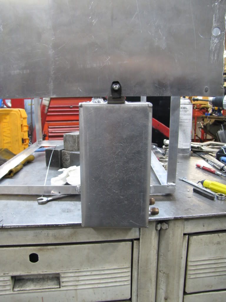
There will be more pictures tomorrow of the finished surge tank (forgot to take pictures today) as well as the mounting of the surge tank, and the plumbing of all the lines.
One of my new tools in my arsenal. This thing makes life much easier. Its probably older than my age*3...
National Box and Pan Hand Break
Another new tool in my arsenal. Again, makes life easier. Here's the setup I had to use to make a box:
Surge Tank Fabrication
Breaking the plate into a box:
Tack welded together
Welded the seam. This one was OK. I went back over the welds without filler rod to ensure that it didn't leak. Normally, I wouldn't do this, but its fuel, and it could be under pressure if there's a failure in the fuel system (nominally, its not under any pressure).
Fabricating the baffle inside. I wanted to make sure there was no possible way for the engine to be starved of fuel, even if the tank was low and I was mid corner, then powering out.
There will be more pictures tomorrow of the finished surge tank (forgot to take pictures today) as well as the mounting of the surge tank, and the plumbing of all the lines.
12-17-09, 08:03 PM
#50
Fabrineer
Thread Starter
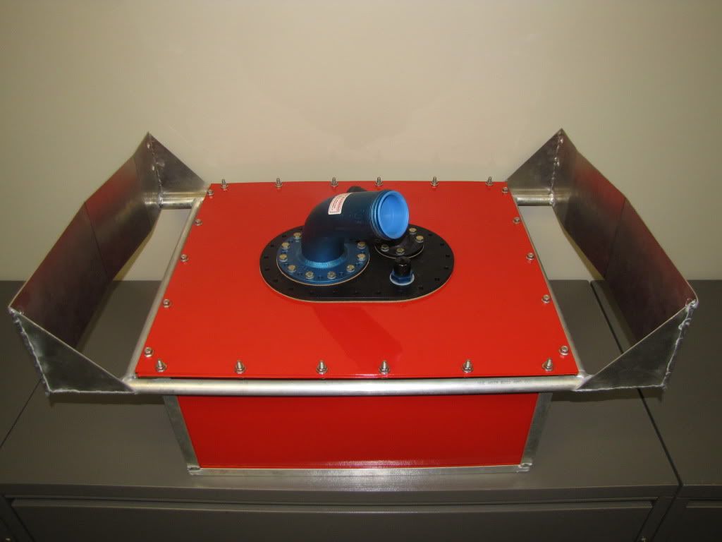
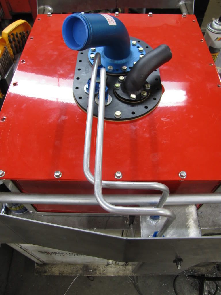
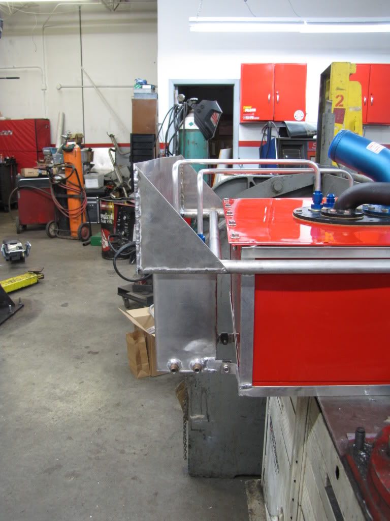
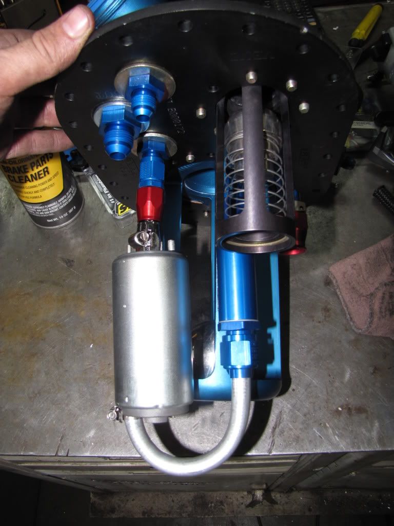
Surge Tank and Fuel Line Plumbing
Finished up the surge tank and mounted it
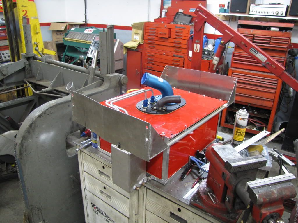
Started plumbing the fuel lines
This is my first attempt at hard fuel lines. I was attracted to these for both price and weight. They are much lighter than the stainless braided line, and somewhat lighter than the nylon braided line.
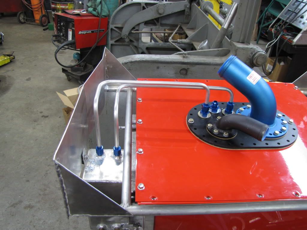

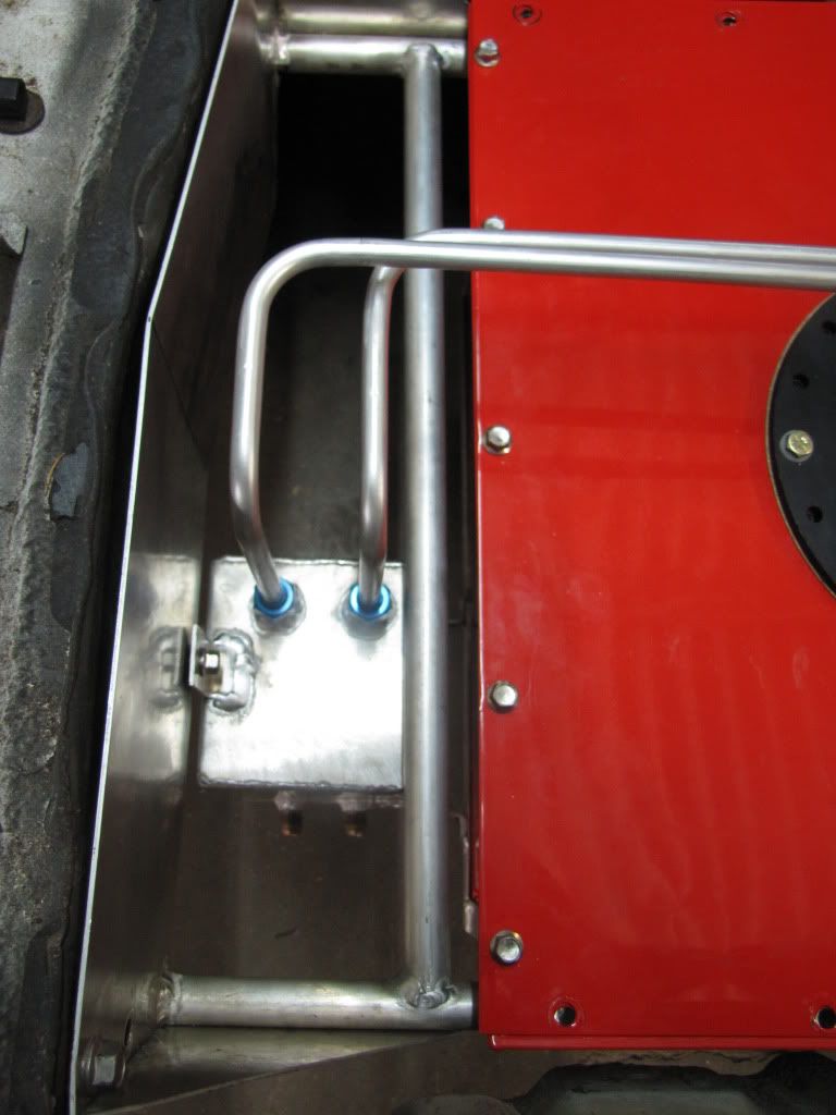
Started plumbing the fuel lines
This is my first attempt at hard fuel lines. I was attracted to these for both price and weight. They are much lighter than the stainless braided line, and somewhat lighter than the nylon braided line.