(Dumb?) Exhaust Manifold Construction Question
 12-08-08, 05:45 PM
#1
Junior Member
Thread Starter
Join Date: Jan 2007
Location: Arizona
Posts: 26
Likes: 0
Received 0 Likes
on
0 Posts
(Dumb?) Exhaust Manifold Construction Question
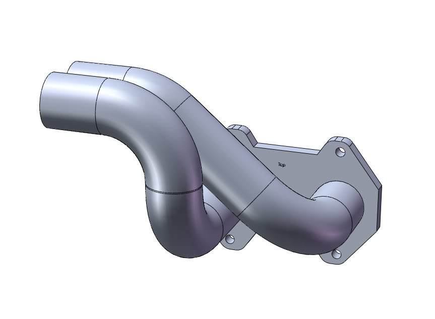
Okay, I'm jumping into the deep end of the pool and am going to build an exhaust manifold for my T04S upgrade (the car is not an RX-7, so I need a custom manifold).
I've laid out the basic piping and made sure I have correct clearances underhood. I'm going with ~17-inch long 2-inch diameter equal length primaries. Everything seems like it will fit well, but when I get to the end the tubing I have a dumb question:
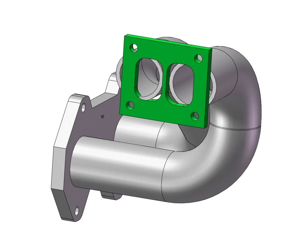
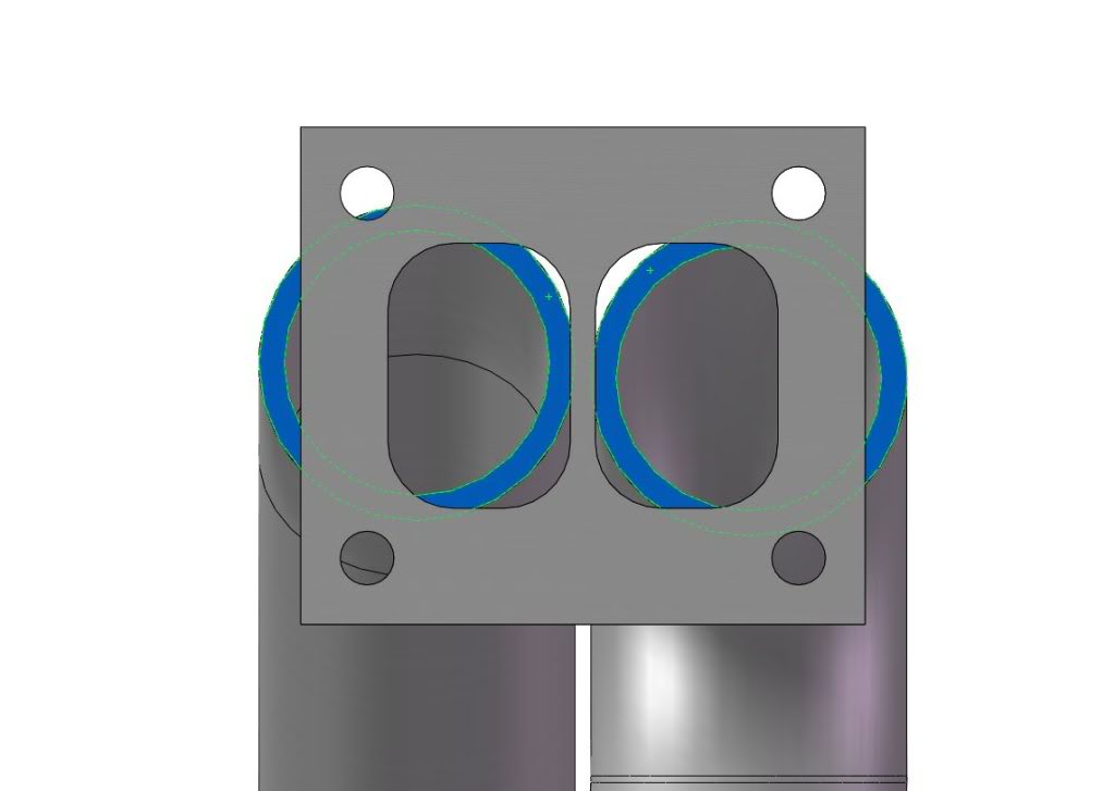
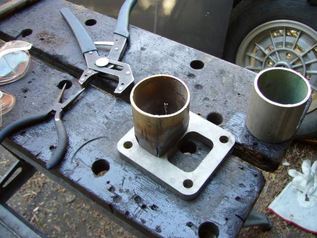
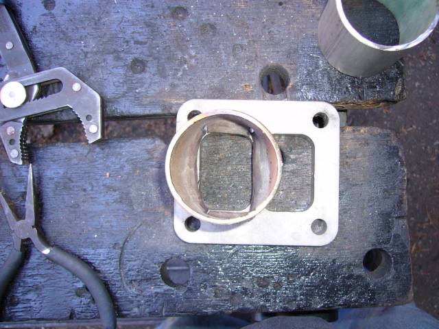
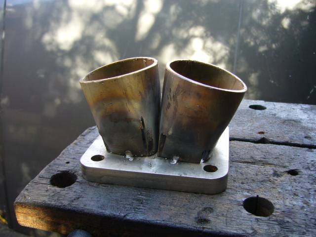
How do I transition from the round 2-inch diameter tubing to the T4-flange, with it's two rectangular openings? I've attached some images below to illustrate what I"m talking about.
What have the rest of you guys done when confronting this problem? Put the end of the tube in a hydraulic press and squish it into an elliptical shape that's nearly the same as the rectangular holes? Use some kind of forming tool to reshape the end of the tube? Or??
Help!
-Bug
I've laid out the basic piping and made sure I have correct clearances underhood. I'm going with ~17-inch long 2-inch diameter equal length primaries. Everything seems like it will fit well, but when I get to the end the tubing I have a dumb question:
How do I transition from the round 2-inch diameter tubing to the T4-flange, with it's two rectangular openings? I've attached some images below to illustrate what I"m talking about.
What have the rest of you guys done when confronting this problem? Put the end of the tube in a hydraulic press and squish it into an elliptical shape that's nearly the same as the rectangular holes? Use some kind of forming tool to reshape the end of the tube? Or??
Help!
-Bug
 12-08-08, 05:55 PM
#2
Learned alot | Alot to go
iTrader: (2)
Join Date: Apr 2002
Location: Rotaryland, New Hampshire
Posts: 4,232
Likes: 0
Received 0 Likes
on
0 Posts
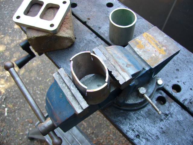
Ive seen people squish them in vices or cut in 4 notches so the pipe can be squared off then rewelded and ground smooth. I plan on doing the notching method with the pile of sched 40 ss i have for my mani.
12-08-08, 07:10 PM
#4
Heat with Torch, squish in vice. If you want more exact meathods, make a matril, then squish it using a press. Make sure you'll be able to get it back out lol. Then theres the messy method of notching and re-welding. Best I've found using sch 40 (or was it sch 10? I dont recall) stainles pipe is simply heat it and use a vise. If your patient, you can get the shape damn near perfect and have a smooth seamless and nice radius in the corners.
~Mike...............
~Mike...............
12-08-08, 07:21 PM
#5
Learned alot | Alot to go
iTrader: (2)
Join Date: Apr 2002
Location: Rotaryland, New Hampshire
Posts: 4,232
Likes: 0
Received 0 Likes
on
0 Posts
sched 40 is like 1/8th wall, im not saying squishing it in a vice cant be done but to me that just sounds like a pita
but if im wrong, that could save me alot of welding
/jacking of op's thread
but if im wrong, that could save me alot of welding
/jacking of op's thread
12-08-08, 07:27 PM
#6
sched 40 is more like 1/4". Have fun beating that into submission, espec. if it's stainless 
If you are using pipe to construct the manifold(like sched 10 or 40), you can buy eccentric reducers if you have the space. The 2.0 to 1.5" reducer is 3" long. But a pair of those make a nice transition to the turbo flange end.
http://www.rjsales.com/products/butt...ial/red10.html
If you are using pipe to construct the manifold(like sched 10 or 40), you can buy eccentric reducers if you have the space. The 2.0 to 1.5" reducer is 3" long. But a pair of those make a nice transition to the turbo flange end.
http://www.rjsales.com/products/butt...ial/red10.html
Last edited by The Griffin; 12-08-08 at 07:35 PM.
12-08-08, 07:28 PM
#7
USE HEAT, then squishing it isn't so bad.
Notching always looks botched up and you get square shapes not too mention you have to flatten out the sides after you notch it right? If you notice, the T4 inlet/flange has radii in the corners. Then theres the "I'll just grind the inside smooth and grind the outside a little" which always comes out like garbage unless you pateint and skilled, in which case, you'd simply use the heat and vice method or a mandrill and press lol.
~Mike..............
Trending Topics
12-08-08, 07:33 PM
#8
Yeah, I've mentioned the reducers in several post before. The 1.5" pipe make a perfect shape for a T4 flange. The 2" pipe is a tad too big. So on my manifold I used the 1.5" to 2" reducers for a nice transition and good fitting T4 junction. I also use the reducers back words for the engine flange too, but thats because I have modified exhaust sleeves . Off topic, dont ask.
Optimumly, mount your wastegate tap for the runners near the T4 flange if space permits. If not, make sure to place the taps at least on the outside of a bend and in the direction of flow. Make sure you do the same for both WG runner taps. I see too many people make nice manifold only to place the WG taps in a shitty spot.
~Mike................
. Off topic, dont ask. Optimumly, mount your wastegate tap for the runners near the T4 flange if space permits. If not, make sure to place the taps at least on the outside of a bend and in the direction of flow. Make sure you do the same for both WG runner taps. I see too many people make nice manifold only to place the WG taps in a shitty spot.
~Mike................
 12-12-08, 09:35 AM
#12
Engine, Not Motor
iTrader: (1)
Join Date: Feb 2001
Location: London, Ontario, Canada
Posts: 29,789
Likes: 0
Received 108 Likes
on
91 Posts
You can see all the pictures here:
http://www.aaroncake.net/rx-7/projec...jun52007-1.htm
http://www.aaroncake.net/rx-7/projec...ul182007-1.htm
http://www.aaroncake.net/rx-7/projec...jun52007-1.htm
http://www.aaroncake.net/rx-7/projec...ul182007-1.htm
12-14-08, 01:55 PM
#13
MAGNUM SE7EN
iTrader: (11)
Join Date: Mar 2001
Location: Asheville, NC USA
Posts: 1,427
Likes: 0
Received 0 Likes
on
0 Posts
Last manifold I made was mild steel and for a 3g prelude. It utilized a t3 flange but similarly you do have to make the transition from round pipe to rectangular flange.
I cut the two pipes vertically at a slight angle and rotate them toward each other slightly. That's it. I'm able to seal the rest with filler rod.
However, I realize you want to maintain the division due to a divided housing.


I cut the two pipes vertically at a slight angle and rotate them toward each other slightly. That's it. I'm able to seal the rest with filler rod.
However, I realize you want to maintain the division due to a divided housing.


 12-25-08, 10:26 PM
#14
Several options discussed here............
https://www.rx7club.com/fabrication-250/twin-entry-custom-manifolds-746512/
BTW, I'm digging the model of the manifold! You've givin me a whole new level of anality to aspire to!
https://www.rx7club.com/fabrication-250/twin-entry-custom-manifolds-746512/
BTW, I'm digging the model of the manifold! You've givin me a whole new level of anality to aspire to!
Last edited by 13brenova; 12-25-08 at 10:38 PM.
 01-13-09, 02:41 PM
#16
Junior Member
Thread Starter
Join Date: Jan 2007
Location: Arizona
Posts: 26
Likes: 0
Received 0 Likes
on
0 Posts
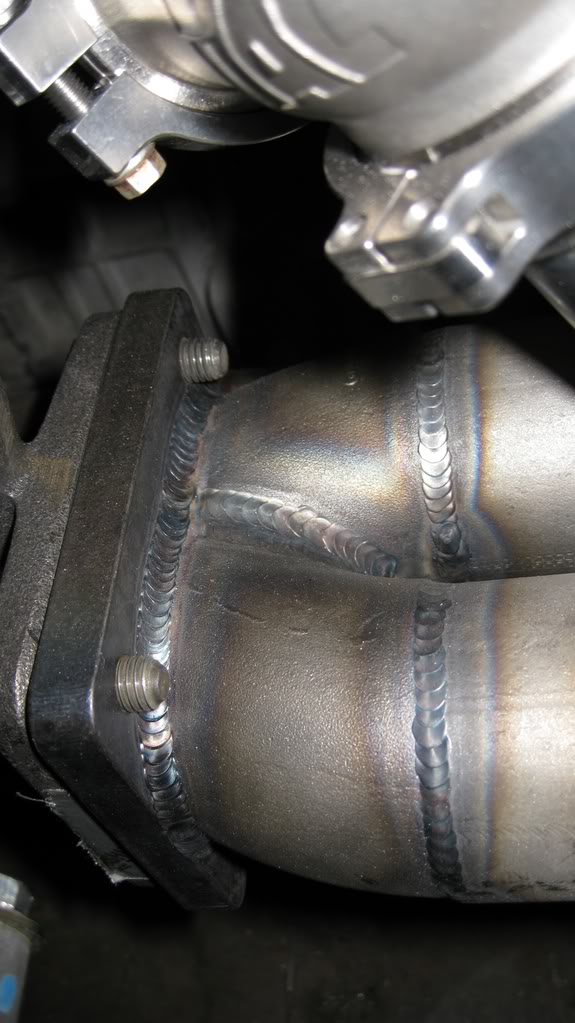
I'm making a big push this week on the exhaust manifold. I cut out all the manifold pieces (2" ID Schedule 40 pipe and weld-els), tacked them up, and then had it all TIG welded up by my fab guru. Turned out really nice, if I do say so myself.
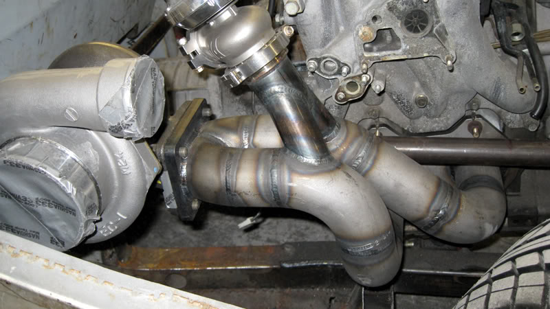
In the end, we decided to go with a "weld-el" approach at the collector. I will still need to do some grinding just inside the turbo flange, but nothing too serious.
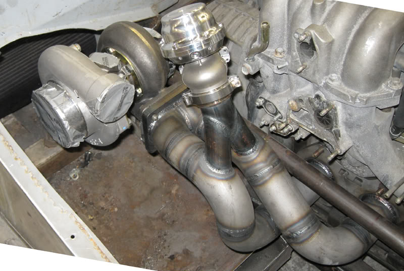
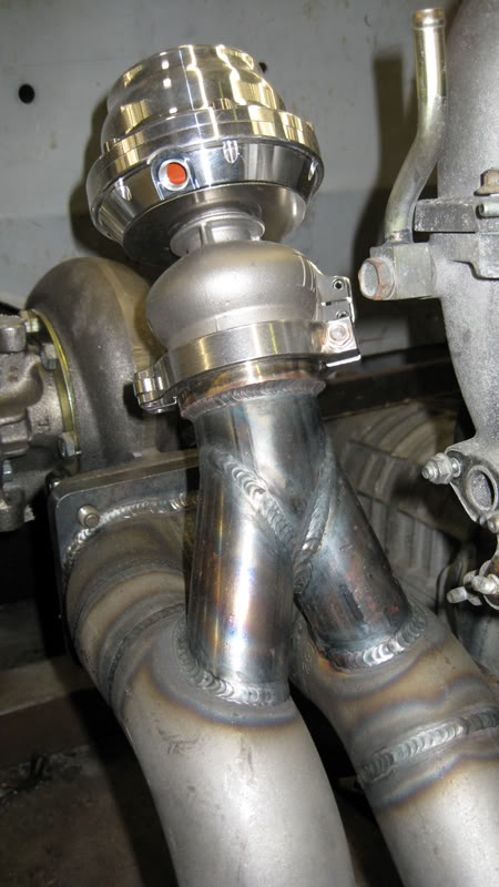
The wastegate is a 44mm TiAL unit. The runners are 1.25-inch ID, 1/8-wall pieces. Note that they're situated on the outside bends of the main runners, where they will get good flow and, therefore, allow for decent control of boost. Way too often it seems that people just stick the wastegate runners anywhere on the main runners, with little regard to flow. Getting a smooth transition into the wastegate is important to controlling flow (and therefore, boost) through it.

Next up is some frame rail mods near the turbo, so that we can start fabbing the downpipe and plumbing the wastegate outlet into the exhaust. Then it's back to the rear of the car and installation of a muffler.
The main question I have at this point is whether I need to brace the turbo end of the manifold any to help support the weight of the turbo. The schedule 40 pipe is pretty heavy duty, but it's been suggested that I will still need some extra support. Ideas?
-Bug
In the end, we decided to go with a "weld-el" approach at the collector. I will still need to do some grinding just inside the turbo flange, but nothing too serious.
The wastegate is a 44mm TiAL unit. The runners are 1.25-inch ID, 1/8-wall pieces. Note that they're situated on the outside bends of the main runners, where they will get good flow and, therefore, allow for decent control of boost. Way too often it seems that people just stick the wastegate runners anywhere on the main runners, with little regard to flow. Getting a smooth transition into the wastegate is important to controlling flow (and therefore, boost) through it.
Next up is some frame rail mods near the turbo, so that we can start fabbing the downpipe and plumbing the wastegate outlet into the exhaust. Then it's back to the rear of the car and installation of a muffler.
The main question I have at this point is whether I need to brace the turbo end of the manifold any to help support the weight of the turbo. The schedule 40 pipe is pretty heavy duty, but it's been suggested that I will still need some extra support. Ideas?
-Bug
01-13-09, 07:38 PM
#17
MAGNUM SE7EN
iTrader: (11)
Join Date: Mar 2001
Location: Asheville, NC USA
Posts: 1,427
Likes: 0
Received 0 Likes
on
0 Posts
Welds look nice!
I feel like bracing, if done properly, is certainly a good idea. I would recommend using a point on the motor since it will have the same travel as the manifold assembly. Maybe it's possible to anchor it to the top of the motor since you will most likely have unused bolt holes in that area.
Keep us posted and good luck!


Thread
Thread Starter
Forum
Replies
Last Post