Fuel Injection Timing Diagrams
 02-27-08, 07:50 PM
#1
rebreaking things
Thread Starter
Join Date: Apr 2006
Location: Manhattan
Posts: 866
Likes: 0
Received 0 Likes
on
0 Posts
Fuel Injection Timing Diagrams
Does anyone have an injection timing END diagram for a rotary engine? I believe the FD uses an injector end timing control method, but I haven't been able to find a diagram for it.
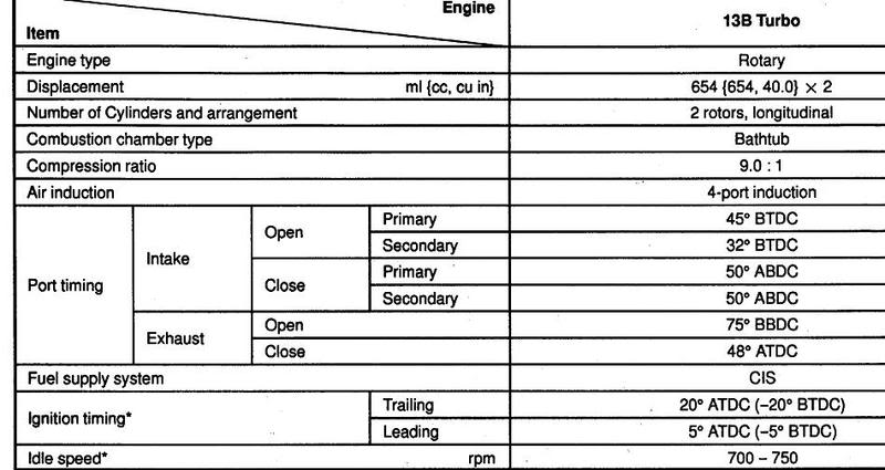
Here is one for the 86 13B, but it appears to use a beginning control method:
Here is one for the 86 13B, but it appears to use a beginning control method:
 02-28-08, 12:16 AM
#2
Corn-to-Noise Converter

iTrader: (6)
Join Date: Mar 2002
Location: The Elysian Fields (Texas)
Posts: 1,527
Received 386 Likes
on
154 Posts
Sorry, no contribution but I'm definintely subscribed.
Would have though that your SQ6 tuner might have had this already. Any ways, I'll ask Paul Yaw next time we talk to see if he has any insights. Might need it in my M4 install.... damn, another thing to learn!
Would have though that your SQ6 tuner might have had this already. Any ways, I'll ask Paul Yaw next time we talk to see if he has any insights. Might need it in my M4 install.... damn, another thing to learn!
02-29-08, 09:31 AM
#3
rebreaking things
Thread Starter
Join Date: Apr 2006
Location: Manhattan
Posts: 866
Likes: 0
Received 0 Likes
on
0 Posts
I should have been more specific. I am looking for a MAZDA diagram. I put together an end injection map myself, but I would like to gut-check it against what Mazda used with the stock setup.
02-29-08, 06:58 PM
#4
rebreaking things
Thread Starter
Join Date: Apr 2006
Location: Manhattan
Posts: 866
Likes: 0
Received 0 Likes
on
0 Posts
Haltech's perspective: "For rotary engines, the typical usable range for injection angle is from 90 to 270 degrees BTDC. Any angles greater than 360 degrees will be interpreted as 360 degrees BTDC." This came from section 3.7 of the E11v2 manual.
03-01-08, 12:18 PM
#5
Corn-to-Noise Converter
iTrader: (6)
Join Date: Mar 2002
Location: The Elysian Fields (Texas)
Posts: 1,527
Received 386 Likes
on
154 Posts
Just spend 20 minutes going through the factory Mazda Technical Highlights Manual, and unfortunately there is nothing there. Though I've often found important insights not covered in the FSM, I came up short.. still looking.
03-02-08, 12:31 AM
#6
I think injection timing should be more important for rotaries than piston engines, but I wonder if you might be giving Mazda more credit than they are due.
1. How do you know the OEM ECU had enough spare processing power to implement a 'good' injection timing map in the first place?
2. Mazda might have made comprimises for emissions and/or fuel economy.
3. You probably aren't using stock injectors or stock port timing anymore.
IMHO, your time might be better spent experimenting. I've done a bit of testing, but not enough to be conclusive. It's something I wanted to come back and test more thoroughly, thanks for the reminder.

Trending Topics
10-10-10, 03:08 PM
#9
Lets bring this back up. I've been trying to set up my staging but I'm having problems. I can get my engine to rev perfectly to red line (no sputters) when I un-click the staged injection icon. So yea the primaries are doing all the work. As soon as I enable staged injection and move the staging bar to a low load region (so I can get them to come on in light loads and adjust the angle) The engine sputters and wont rev. My secondaries are mounted about 4" higher up the runner than on the factory 20b LIM. I'm using common mode. I've tried adjusting the angles up and down while holding the revs at 2k but cant get it to run smooth at all when they kick in. I have noticed that my injection times for secondaries are the same as the primary. Thinking it was over rich, I lowered the mS values in the 2k region in half but it still doesn't help. I'm running the factory 20b primary and secondary 550cc injectors. Now my engine is still on the test stand so I don't know if not having any engine load is why it's doing this?
Just realized this wasn't the Haltech section.
Just realized this wasn't the Haltech section.

 03-25-13, 10:17 PM
#11
yessir
iTrader: (24)
Join Date: May 2005
Location: Sebring FL
Posts: 722
Likes: 0
Received 0 Likes
on
0 Posts
Ok,
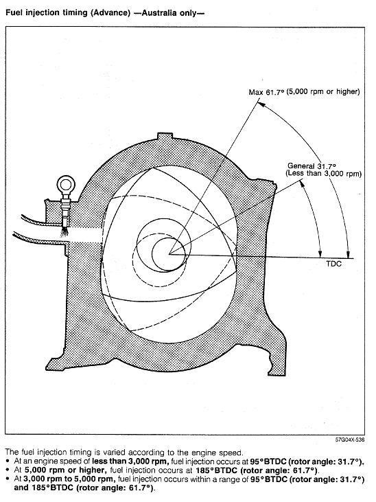
1. It took me awhile to notice this correlation but, the "fuel injection timing - Australia" article from the top says it uses 95 BTDC below 3000 rpms.
The "09+ Rx8 fuel injection timing" article says they use 95 BTDC (455minus360) during cranking, but seems to refer to a very smooth inj. end position vs rpm table immediately after 500 rpms. Just found it funny, sometimes much doesn't change.
2. Would anyone happen to to know the velocity of the air/fuel at various rpms? I figure you can do the math on how many milliseconds each degree of timing is worth at various rpms, and calculated with the fuel speed and exactly how far from the port the injectors are, you might be able to figure it out. You'd also have to account for the secondary ports opening sooner.
3. My ecu supports beginning, middle and end of squirt timing. Middle of squirt timing seems to me like it would make it easier to better time the pulses of fuel, compared to an end of squirt algorithm. Or is the injector pulse width so short it really doesn't matter? Can anyone elaborate?
05-11-13, 09:21 PM
#12
Senior Member

Injection timing is one of those things that can defy all of your preconceived notions about engine dynamics.
When I first set up sequential injection (4cyl piston engine)my thought was that you would want to inject the fuel into the moving airstream while the valve was open.
I quickly realized that "it don't work that way"!
As it turns out you want to inject the fuel against the back of a closed valve. So the timing is set to end just before the valve opens until the duty cycle gets so large that you have to "back it up" well into the intake stroke. It seems that injecting into the moving air stream stratifies the charge so that it is not mixed well enough for complete combustion.
This mazda chart gives us a good starting point, but it sure would be nice if someone could fill us in on the details of the dynamics so we could use some reasoning for our adjustments instead of just playing with it til it seems about right.
For instance...
and I'm probably wrong...
It looks to me like there is only 270deg crankshaft to inject a full cycle of fuel into.
If that is so my perception of duty cycle is way off for a rotary
Last edited by Vicoor; 05-11-13 at 09:50 PM. Reason: adding thoughts
07-09-13, 04:30 AM
#13
Senior Member
Join Date: Nov 2008
Location: Czech republic
Posts: 357
Likes: 0
Received 0 Likes
on
0 Posts
Corrrect way to set up injection angle at any given load and speed is through dyno testing. Targeting for certain AFR and then adjusting injection angle until richest output lambda is observed - most of the given fuel amount contributes to combustion.
Still, to have really good control over air-fuel mixture inside chamber, one would have to use large fuel injectors and high pressure, to operate at much lower duty cycles than are usually considered as "safe". They may be safe from standpoint of injector itself, but aren't safe from control standpoint of charge preparation for each rotor flank. It may work ok in normal situations, but overboost fuel cut or traction control fuel cut when one injection pulse can overlap two chambers would cause certain issues
Still, to have really good control over air-fuel mixture inside chamber, one would have to use large fuel injectors and high pressure, to operate at much lower duty cycles than are usually considered as "safe". They may be safe from standpoint of injector itself, but aren't safe from control standpoint of charge preparation for each rotor flank. It may work ok in normal situations, but overboost fuel cut or traction control fuel cut when one injection pulse can overlap two chambers would cause certain issues
07-11-13, 03:49 PM
#15
Senior Member
Join Date: Nov 2008
Location: Czech republic
Posts: 357
Likes: 0
Received 0 Likes
on
0 Posts
I should make clarification, richest output reading with given pulsewidth doesn't inherently mean most efficient combustion and/or highest torque production. Its just measurement of what is after combustion, but it still should indicate right direction in optimizing setup.
Injection timing giving most torque from given amount of fuel is of course best measure of efficiency.

Thread
Thread Starter
Forum
Replies
Last Post
trickster
2nd Generation Specific (1986-1992)
25
07-01-23 04:40 PM