When you click on links to various merchants on this site and make a purchase, this can result in this site earning a commission. Affiliate programs and affiliations include, but are not limited to, the eBay Partner Network.
John I agree that driving a stock 4 rotor is pointless. I would drive a semi p port one and if I got 20k+ miles out of it I would probably be ok with that. I usually don't drive more than a couple thousand miles a year on my RX-7. So considering that would be 10 years worth of use for me it's not so bad.
I'm not sure the main bearings being out of alignment is that big of an issue. When all is machined well it should be concentric within 0.01-0.02mm's or so, and it really doesnt take any effort to "bend" an e-shaft that much, you can do it with one finger.
I don't have any doubt about your machining skills, but I was thinking you weren't thinking on what a slinky the stack of a 4 rotor is.
One distortion that is going to be the easiest to figure out is the effect of thermal loading.
These illustrations show Mazda's findings of rotor housing temperature distribution. Take the 70C delta and multiply that by the coefficient of expansion of the Aluminum rotor housings and multiply that by the length of the 4 rotor housings and you are going to have ~ 0.02" distortion.
You will have to model your rotor housings, side housings and tension bolt clamping to see what shape your 4 rotor slinky stack takes and where the bearing centers end up.
That is one force acting on the slinky.
Another is the gas pressure acting on the rotor housing. Again, you can model the engine, distort the rotor housings according the forces and see how that force transfers into the end housings through the two dowel pins (at near opposite extremes of the forces) and affects bearing centers.
Add that to the thermal distortion, find the next force acting on the engine stack...
My point is the Mazda rotary is a slippy slinky of a stack of housings and on the 3 rotor and 4 rotor with more than 2 bearings to line up- making the eccentric shaft more rigid will weaken the motor, making the shaft more flexible will strengthen it.
The most likely reason you don't see 4 rotors running for a long time on the street is because they don't exist in street cars to begin with; so there's just no data.
Talking to Brent Curran in NZ, his drag car motor, which may have been ebuilt a few times from running 40psi lol, he has pictures of the bearings and is using the same bearings from day one. These are the same e-shafts sold by jeff at precision. Same used by PPRE, same used by CLR.
I'd bet at street rpms, there's not that much wear on these motors, and they'd last fairly long assuming the engine builders set it up correctly.
I can only hope my engine was built correctly so I dont want to comment on mine.
But looking at engines that Carlos Lopez has built, where he talks about how to clearance the outer bearings to allow for shaft flex, and using high oil pressure then usual to "float" the bearings, then running these engines above 10k rpm at the track, seems hopeful that it is possible a 4 rotor could would work on the street for a long time at lower rpms around town. After hearing this advice from Carlos I immediately pulled the subframe/oil pan and shimmed off the regulator for 125psi and set the oil pump for higher pressure
When I pull the transmission off for upgrade, will be sure to get some pics of rear bearing
John I was talking with another forum member the other day on the phone about this thread. You are an absolute genius/artist. Its amazing and inspirational how you can do all of this. Can't wait to see more.
There is a big difference between race reliability and consumer longevity.
A racer thinks a season or two of racing would be great between refreshes, but a consumer expects an engine to last 200,000miles unopened.
I am pretty sure I read Yuki gets 30,000miles between overhauls on his Scoot built 4 rotor and they build their shafts up like Mazda R26B (2 rotor +1 front, +1 rear).
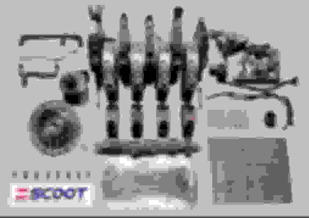
Correct me if I'm wrong, but that scoot engine looks like the center 2 housings are assembled with those long dowels and the tension bolts secure it from both ends? Do the tension bolts thread into the long dowels?
I think the dowels are just dowels, though I see a set of shorter dowels. Dowels are threaded so you can take them out with the factory dowel puller.
The engine looks like it is put together easiest "backward" with the 3rd rotor down and stacking 2nd and then 1st on top, put front short tension bolts in and then flip the motor and stack the 4th rotor on and put in the rear short bolts and the long through tension bolts.
There's eight dowels in the pic, a 13B has four, it's probably three long and one short and has to do with the stack-up of the engine. Also, the tension bolts look more like they double as studs. How else could you thread a tension bolt into a 13B center plate?
John I agree that driving a stock 4 rotor is pointless. I would drive a semi p port one and if I got 20k+ miles out of it I would probably be ok with that. I usually don't drive more than a couple thousand miles a year on my RX-7. So considering that would be 10 years worth of use for me it's not so bad.
A Semi-PP one would be great! I haven't seen one yet though.
Originally Posted by Lavitzlegend
Wait, you're going overboard on a 13b build??? No way... You're going to post pictures and results of what you are doing though, right?
Well it's not completely overboard, but here is what happened. I first disassembled the US-spec 6-port that came in the FC I bought. When it was all disassembled I looked at what needed to be done, and I somehow got it in my head to convert it to 4-port, just because I like the 4-ports better. So I went through my rotary parts, and the only complete FC sets I had were a set of late thick S5 TII housings, and a set of S4 TII housings with some rust because they came from an engine that blew a waterseal and sat for a while. The lare S5 one is perfect for a turbo engine, so I figured I'd try to revive the S4 ones first, so I carefully dialed them in on the late, and ground about 0.03mm's off:
That removed all of the high-spots and got rid of most of the rust and wear. After that I lapped about 0.02mm's of, and they came out great :-)
Next I thought about intakes, and porting and whatnot, and I didn't want to spend a lot of time porting, so I left the ports in the iron stock and did this instead:
It's the first time doing a semi pp, so I tried it on a junk iron first. I didn't want to mess around with devcon putty, so I tried an aluminium bushing with radial o-rings to seal it off. But it didn't want to assemble, it would push the o-ring out causing it to rip:
I tried a few bushings, and some different tolerances and o-rings, but couldn't fix the issue, so I machined the good rotor housings differently, and now use inserts that use an axial viton o-ring for sealing. Assembles fine, Im sure it will work. No devcon, and the coolant is still able to flow through the waterpassage near the intake.
After this I removed the diffusers in the exhaust ports. I have about 6 good turbo rotor housings, but I'd rather use them on a 4-rotor or something like that, so I modified the N/A housings, easy job.
Next up I started thinking about an intake. the 6-port one obviously won't work, so I looked on ebay, ordered some stuff, did some machining, and this is pretty much where I am now:
So, the throttlebody is from a BMW motorcycle. it's 42mm's in diameter, and being BMW, it uses bosch injectors, sensors and connectors. Easier for me than japanese stuff that uses denso. The flange is about 3/4" thick and the holes taper from the 13B ports to round ports, so making an intake is super easy. The outer holes match the diameter and spacing of the throttlebody. I need to do some metal fabricating for the middle and PP ports, but its not so bad.
So to be continued. Hope to assembly the engine tomorrow or saturday. The internals will be mostly stock. The apex seals are changed from 3 to 2-piece, the corner springs are the wider type, the waterseals are the 2.4 and 2mm viton ones I usually use and the stat gears, bearings and oil pump will be FD items. Clutch will be the lightened OS-giken one borrowed from the 4-rotor. ECU will be my old microsquirt.
Originally Posted by BLUE TII
[I]
.....
Nice pictures, haven;t seen those before. Maybe that's why the 787B uses such a thick plate under the engine? I don't remember exactly but I think the SAE paper said it uses a 1" thich alloy plate with a honeycomb structure, so it stiffens the engine up without adding a bunch of weight.
Originally Posted by Monsterbox
The most likely reason you don't see 4 rotors running for a long time on the street is because they don't exist in street cars to begin with; so there's just no data.
Talking to Brent Curran in NZ, his drag car motor, which may have been ebuilt a few times from running 40psi lol, he has pictures of the bearings and is using the same bearings from day one. These are the same e-shafts sold by jeff at precision. Same used by PPRE, same used by CLR.
I'd bet at street rpms, there's not that much wear on these motors, and they'd last fairly long assuming the engine builders set it up correctly.
I can only hope my engine was built correctly so I dont want to comment on mine.
But looking at engines that Carlos Lopez has built, where he talks about how to clearance the outer bearings to allow for shaft flex, and using high oil pressure then usual to "float" the bearings, then running these engines above 10k rpm at the track, seems hopeful that it is possible a 4 rotor could would work on the street for a long time at lower rpms around town. After hearing this advice from Carlos I immediately pulled the subframe/oil pan and shimmed off the regulator for 125psi and set the oil pump for higher pressure
When I pull the transmission off for upgrade, will be sure to get some pics of rear bearing
John I was talking with another forum member the other day on the phone about this thread. You are an absolute genius/artist. Its amazing and inspirational how you can do all of this. Can't wait to see more.
Thanks a lot! Hopefully one day mine will sound as awesome as yours You really pulled it off in a short amount of time, I'm jealous.
Originally Posted by TonyD89
There's eight dowels in the pic, a 13B has four, it's probably three long and one short and has to do with the stack-up of the engine. Also, the tension bolts look more like they double as studs. How else could you thread a tension bolt into a 13B center plate?
The center plate probably has threaded inserts in there. This makes the assembly easier.
My engine stacks differently, rear to front, so this isn't needed for me, but it makes perfect sense for a normal 4-rotor.
Last edited by John Huijben; 03-23-17 at 05:26 PM.
In the Scoot pic, comparing the tension bolts to the dowels, I don't believe they are 10mm. I'm betting 12mm and then that is more machining and why wouldn't you run them like the aftermarket oversized stud kits that have only .004" (.1mm) clearance? That wouldn't require a threaded insert in the center plate, just machining to a 12mm or 1/2" thread, whichever is your cup of tea.
There is a big difference between race reliability and consumer longevity.
A racer thinks a season or two of racing would be great between refreshes, but a consumer expects an engine to last 200,000miles unopened.
Mazda ran Lemans with theirs, pulled it apart, measured for wear (apex seals had zero), put it back together, and then ran track days with it until 2012, when they refreshed it again, and took the restrictor out, so they could vintage race it.
20 years between rebuilds is pretty good! especially when its at a racetrack somewhere every other weekend.
also don't forget the R26B has the big top and bottom braces, so they can use it as a stressed member in the chassis
I'm planning to do something similar in the next few months for my full bridge but I'm going to try some Ducati TBs instead and since I'm not PP or semi PP I will just use ID1000s in the primary position only. How did you decide on 3/4" thick? To keep the taper to a certain degree? Is the additional metalwork to open up the tops and bottoms on the engine side of the adapter? Also, most of your pictures are not showing up for me...
Last edited by Lavitzlegend; 03-24-17 at 09:34 AM.
I read a 7tune article a while back about a white FD in Japan that some younger gent owns that he commutes and tracks. They were saying in the article how it has a map to run on 2 rotors, somehow, to help with the longevity of the engine. It didn't say how long the car went between refreshers but it seems like there is a steetable 4 rotor out there that is not owned as a promotional piece for a shop.
Yes. that is Yuki Kamakura's FD that I referenced and linked.
20,000miles between rebuilds with 10,000rpm redline or 30,000miles between rebuilds with 8,000rpm redline is what he told Adam Zillin (published articles as 7Tune, Speed Hunters and the Pass Mag article that I linked).
These ones are from a BMW K1200S 2004-2008, I believe there is also a K1200LT which is reasonably similar, but a smaller diameter, so you want the K1200S or RS throttlebodies.
There is a stepper mounted to these, which acts as a throttlestop, so it limits how much the butterflys can be opened. Probably for engine warm-up or something like that. Just two bolts to remove though.
Spend my friday evening assembling the little semi pp engine. Even though it's missing a bunch of rotors I just can't help getting a teeny little bit excited :-),
Yes, N/A Semi PP, trying to get this thing running without too much time or money involved. The idea is to test the new water / oil coolers, dry sump setup, and ecu with this engine first, so that when the 4-rotor is back together, a lot of the kinks are already worked out.
Had a little time last weekend. Engine is all dressed up, and in the car :-). Got some of the stuff bolted up, but still need to do the cooling, some wiring, and finish the ITB setup.
Damn... That is awesome but looks time consuming! What size are the inlet tubes? 1.75"?
Yeah, it's hugely time consuming. Its just about ready to go on the car now, but I probably have around 12-16 hours in it. For example, I just got done machining the flange that mates to the engine, and it took me 1.5 hours . Mostly because the now welded intake is awkward to mount in the mill, but still.
The motorbike throttlebody is 42mm ID, and the outer runners match this. The inner runners start at 42mm, and tapers down to 37mm at the flange, but these split into the PP-runners aswell, which are 26mm ID. The P-port is 26mm aswell. I made the intake length as short as practically possible, because its easier to set the length by using appropriate length velocity stacks. Shooting for around 380mm total length.
 03-22-17, 09:39 PM


 You really pulled it off in a short amount of time, I'm jealous.


 . Mostly because the now welded intake is awkward to mount in the mill, but still.