When you click on links to various merchants on this site and make a purchase, this can result in this site earning a commission. Affiliate programs and affiliations include, but are not limited to, the eBay Partner Network.
The outside perimeter isn't the problem though, because if the wear plate is a little bit thicker than the pocket in the machined piece, than the rotor housings will clamp it in place. I was wondering about how to fix it in place a the inside bore,
Mmm... ehhh... humf... I just don't like that , what seems to be an easy solution, I hear this so much in other things and I just like things to be right. I was thinking of leaving the insrt ever so proud and grinding it after installation. .010" nitride is not that expensive. We use it at work and I could slip them through, if you know what I mean. Dust grind them after installation, bam! I think I would make a frame for nitriding that held the insert where the housing covers it and on the diameter in the center that the rotor doesn't get to.
I think this way so I could use o-ring seals still. You would have to seal all those tension bolt holes if the insert is proud. How long do you think the sealant will hold up? You could oring all of of them, that would be better. Maybe one track that curves and goes around each one and use o-ring cord stock? Vee groove to help hold it?
Your aluminum side plate has a lot of water and not much return room for oil. The stock ones are pretty generous in the oil flow to pan on the intermediate housing since this is the main path for oil return from the rotors. The front plate has a generous opening for the front case stuff but the other passage and the one in the rear plate are only for bearing leakage.
Nice looking CAD stuff though. I like the way you're holding the gears too. I always wondered how the do it on an existing housing.
I noticed in your CAD drawing that the intake ports are at a 45 degree to the bottom instead of the usual straight up and down. Is that for better airflow and tumble into the ports?
It's done for two reasons, the first one is that it makes the port runner larger. Since the port runner cannot be wider it needs to be higher for more area, and if I put it at an angle it's higher and still matches up with the port without tapering or anything.
Second reason is that it should free up a bit of room near the exhaust. I want to be able to fit a turbo later on, and with a 4-rotor you need al the room you can get, so this will help.
Originally Posted by TonyD89
Mmm... ehhh... humf... I just don't like that , what seems to be an easy solution, I hear this so much in other things and I just like things to be right. I was thinking of leaving the insrt ever so proud and grinding it after installation. .010" nitride is not that expensive. We use it at work and I could slip them through, if you know what I mean. Dust grind them after installation, bam! I think I would make a frame for nitriding that held the insert where the housing covers it and on the diameter in the center that the rotor doesn't get to.
I think this way so I could use o-ring seals still. You would have to seal all those tension bolt holes if the insert is proud. How long do you think the sealant will hold up? You could oring all of of them, that would be better. Maybe one track that curves and goes around each one and use o-ring cord stock? Vee groove to help hold it?
Your aluminum side plate has a lot of water and not much return room for oil. The stock ones are pretty generous in the oil flow to pan on the intermediate housing since this is the main path for oil return from the rotors. The front plate has a generous opening for the front case stuff but the other passage and the one in the rear plate are only for bearing leakage.
Nice looking CAD stuff though. I like the way you're holding the gears too. I always wondered how the do it on an existing housing.
Hmmm why would the tension bolts need sealing? I'm planning on using the stock inner and outer water seals, and just adding one o-ring for the return oil pocket, and one where the intake port runner meets the insert, and that's it.
I can see having the insert shrunk fixed with the rest seem like a good idea, but I see some problems with that aswell, like sealing the oil pocket and intake port. Nitrating without affecting the aluminium seems difficult aswell.
You may have a point about the oil return hole being too small. It's a 25mm hole, probably not a problem for the center housing with the bearings, but maybe small for the intermediate housings. I can add another 25mm hole in there.
OK. I am thinking your insert goes under the the rotor housing, if proud, the coolant can leak at the difference into the tension bolt holes unless you use a sealer. Pick .05 mm ( I converted, just for you). It will never be zero (or close, there is no zero) at the junction of the two. I was just saying sealer is sealer and there will always be a transition gap in that design.
Ahhh right, I see what you mean now. It's no problem, it's normal for water to get to the tension bolts. That's why they have washers with rubber seals on them, to prevent from water leaking out from behind the flywheel. I tweaked the design here and there, and I think I've got something drawn up that will work. Already ordered aluminium and cast iron, and the needed tooling. Figuring out the cam now, it's going to be awesome :-)
You know i was reading back a couple pages and noticed your iron wear plates with those dive tails. How would thermal expansion affect the groove over time? Would the slight frictional force from the rotor on the plate cause enough vibration to ream out the groove? If you reduce the tolerances in the groove won't the thermal expansion of the plate alone fracture the housing? Have you considered compacted graphite iron for your wear plate?
Hmmm, I think the grooves will be fine, I changed the design though.
Compacted graphite iron might work, but I don't know where to get it, and how suitable it is for nitrating. I already have material for the wear plates, it's GGG60 a ductile iron, should already be a nice upgrade over stock.
Had half a day to myself today, so I had some fun machining the middle housing. Didn't get as far as I hoped, but didn't scrap anything so thats good :-). Started with a fixturing plate, so I can easily mount, remove and flip the aluminiium billet. It's bolted to the machine-bed, and dowels keep the aluminium in place so nothing can move around. One M16 bolt pulls the billet down in place.
Machining went pretty well. I got most of the material roughed out, so hopefully I can do some contouring and finishing tomorrow. This is a 6082-T6, and it machines heaps better than that gummy crap I had lying around in the shed, With that gummy stuff I really had to babysit the machine because sometimes an endmill would get gummed up and stuck, but with this I can press go, walk away, and come back an hour later without problems . This machine is slow (5000rpm, max feedrate is 80ipm), so it runs at maximum speed and feedrate all the time.
Didn't get as far as I hoped, but didn't scrap anything so thats good :-).
Wow! moving along fast on the new stuff!
When CNC was getting big I worked with a guy and he had a saying "CNC, now we can produce scrap at a rate never before possible". Don't get me wrong, I love it and live by it, but he did have a point. Things happen fast and that red e-stop button is usually useless.
Yeah, I couldnt agree with that more :-), It's a really evil machine that doesn't care how much time and effort your have invested in the workpiece. If you tell it to do something stupid it's really going to do something stupid. In the beginning we had a buggy postprocessor, so even if you did everything right it would still mess up sometimes.
Today went very well. Usually I start thinking about the cad-cam program once the workpiece is in and the machine is ready to go and I end up quickly clicking some stuff on the pc to get it going, but today I planned ahead and spend some time on the programming, and as a result everything went very well. It was completely boring, but boring is good. I ended up watching a movie while the machine worked on my part :-). The middle housing is now almost finished, except for the intake ports, and oil holes, which I'll probably do later because I need to figure out a fixture for those.
Getting it running again first though, which, since I'm constantly changing my mind and doing non-productive stuff will probably take a while
Did some more machining after work, the basic shape is done, still needs intake ports, oil feed and drain, a few o-ring grooves and some finishing where the stat gears go. Total machining time on this one so far is about 10 hours, but I can probably get it down to about 6-7 for the next two ones.
I wonder what a good solution for an intake manifold is. I obviously can't use the stock one, so I will need to make something, but it's not going to be easy because the ports are so high and narrow. It would be ideal if I can make something that transitions from the wierd port shapes to evenly spaced 45mm round holes. Then I can decide later if I want to buy ITB's, build ITB's, or do a plenum intake. The port shape would look like this:
But how to make something like that. I can try getting an aluminium bend and putting it under the hydraulic press, but I doubt it would come out looking anything like that shape . 3D printing would be easy, but probably won't last in this application. cnc-machining could work, but would be a nightmare, it would need to be machined in 3 parts, with curved splitting lines, and then welded together. Hugely wastefull and time consuming.
you can also shape a foam core (CNC or by hand) and laminate carbon fiber/epoxy around it. Once cured you can melt out the foam. The interface flanges can be machined and formed right into the laminate. Just be sure to use a layer of fiberglass in between the carbon and aluminum otherwise you'll have galvanic corrosion on the Al.
Yeah you already played with casting the iron, intake runners would be much easier. I think you're screwing your intake velocity with the shape of the intake runner inside the iron though. I'm thinking it should gradually sweep more instead of being a fixed radius fillet. I didn't want to say anything since you already had it cut... but now since you're talking about efficient runners... you could always make an insert.
Mutiple options out there :-), Never tried casting, kindoff would want to spend some time messing with that, and the same goes for laminating carbon. But it's tempting to sticking with what I know and getting on with it. I did some drawing:
There are two designs, one looks nice, and flows from the port to a nice round shape. Looks good, flows good, total nightmare to build. I tried dividing the part into three and doing some cam, and it really sucks. The parting lines are all curved in all directions so just thinking about fixturing this makes my head hurt.
The second part looks not as good, and transitions not to a round hole but squared hole with rounded edges. Straight parting lines, so easy to fixture and machine. About �30 in aluminium and about 2.5 hours machining time per runner pair. No risky operations or anything so the mill would run pretty much unattended.
Originally Posted by SpeedOfLife
Yeah you already played with casting the iron, intake runners would be much easier. I think you're screwing your intake velocity with the shape of the intake runner inside the iron though. I'm thinking it should gradually sweep more instead of being a fixed radius fillet. I didn't want to say anything since you already had it cut... but now since you're talking about efficient runners... you could always make an insert.
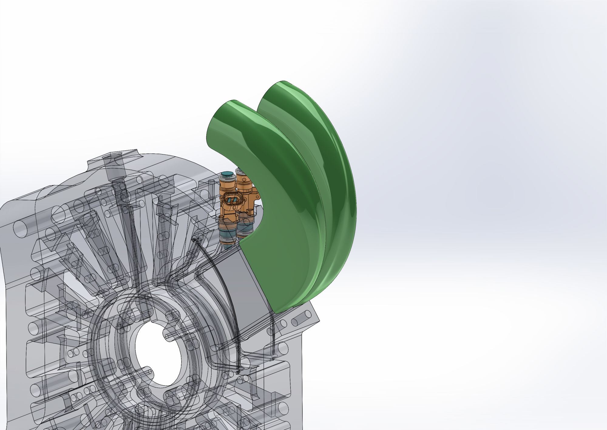
You mean the green coloured radius in this picture?:
It's indeed a simple radius, 12mm's in size. I'm not an expert in this, but with the limited space available having a larger sweep costs some port area, so it's a tradeoff. I did mess around with flowworks software by entering the mass flow (borg warner matchbot is handy for this) and viewing pressure drop over the port/runner, and I tried some different stuff, but having everything as big as possible gave me good results, especially with boost and high mass flows. Now the sim doesn't account for a lot of things, like fuel atomisation, the moving rotor, pressure waves, acoustic stuff ect. so it could be way off. In reality I think it's not that big of an issue.
hmm judging from the last section pic. the inner radius could also use some love. ideally if you are anyway building an engine from scratch you could make the iron a bit wider than 50mm, allowing for a much nicer port design (much like secondaries)
Think about actually being able to bolt the manifold on the engine.
Based on this pics, it looks like you have hardly any clearance to fit a fuel rail, much less fit you fingers in to tighten bolts. You may need to have an "upper" and "lower" section. If that's the case, you can have several different types of uppers to play with. Say, a flanged unit for ITB's, A tubular unit, a large volume plenum, etc.
With the design as it sits, you would need to make a hole right in between the runners to fasten the upper intake bolt.
You mean the green coloured radius in this picture?
It's indeed a simple radius, 12mm's in size. I'm not an expert in this, but with the limited space available having a larger sweep costs some port area, so it's a tradeoff. I did mess around with flowworks software by entering the mass flow (borg warner matchbot is handy for this) and viewing pressure drop over the port/runner, and I tried some different stuff, but having everything as big as possible gave me good results, especially with boost and high mass flows. Now the sim doesn't account for a lot of things, like fuel atomisation, the moving rotor, pressure waves, acoustic stuff ect. so it could be way off. In reality I think it's not that big of an issue.
It's not a big issue, just with the kind of time you've put into this... I know if it were me I'd be trying to extract every bit of power out of the final design as possible. Improving port flow could potentially give you a .5%-2% increase. Also, weren't you doing peripheral port before anyway?
I'm not well versed in fluid dynamics, but I picked up some basics in engineering. You want to avoid sharp bends and sudden changes in shape and cross section area of your pipe. The runners you've drawn would be nice. They have gradual tapering and wide bends. The iron ports don't, you'll add turbulence (flow resistance) right when the intake charge is crashing into that fillet landing. Anyway, you're probably right, not that big of a deal, especially if you strap a turbo(s) on it later. It'd be easier to explain in person, too.
hmm judging from the last section pic. the inner radius could also use some love. ideally if you are anyway building an engine from scratch you could make the iron a bit wider than 50mm, allowing for a much nicer port design (much like secondaries)
Yeah it will have a radius, just not sure if I do those cnc, or by hand manually later. Haven't gotten around to start on those yet, just modelled enough to finish the aluminium piece so I could start on that. Starting from scratch you would make them 80mm wide, like a 20b, but requires a new e-shaft so thats out.
Originally Posted by ACR_RX-7
Think about actually being able to bolt the manifold on the engine.
Based on this pics, it looks like you have hardly any clearance to fit a fuel rail, much less fit you fingers in to tighten bolts. You may need to have an "upper" and "lower" section. If that's the case, you can have several different types of uppers to play with. Say, a flanged unit for ITB's, A tubular unit, a large volume plenum, etc.
With the design as it sits, you would need to make a hole right in between the runners to fasten the upper intake bolt.
Yeah, true for sure. Still needs tweaking and detailing, I want to add a hole in the middle for a inbus socket to go through, and add o-ring grooves, some more room near the bolt heads aswell. I do want it to wrap around as tight as possible though because now that it's dry sump, and the front cover is much flatter, I want to try putting the engine towards the rear and dropping it down. This puts the last intake runner in the transmission tunnel, so having it more compact will be good.
Originally Posted by SpeedOfLife
It's not a big issue, just with the kind of time you've put into this... I know if it were me I'd be trying to extract every bit of power out of the final design as possible. Improving port flow could potentially give you a .5%-2% increase. Also, weren't you doing peripheral port before anyway?
I'm not well versed in fluid dynamics, but I picked up some basics in engineering. You want to avoid sharp bends and sudden changes in shape and cross section area of your pipe. The runners you've drawn would be nice. They have gradual tapering and wide bends. The iron ports don't, you'll add turbulence (flow resistance) right when the intake charge is crashing into that fillet landing. Anyway, you're probably right, not that big of a deal, especially if you strap a turbo(s) on it later. It'd be easier to explain in person, too.
I agree, but when the available space is so limited you have to compromize. Maybe you would choose a little different shape, thats fine. It was PP yes, but in a nutshell. Couldn't get it fully street legal (as in, fully re-registered and having the engine code, displacement and power matching with the car's title), and track days will be difficult aswell because of the noise. Also depends on track though.
Originally Posted by JK5S
John, when did you say you will make a rotary parts kit available to the public?
Not going to happen. I like messing around with this stuff as a hobby, but as a business I think it would suck.
too late now, but would have thought it would have been interesting to run direct injection through the end plates (and mid plates on an angle) and inject into the side of the top chamber. **** off all the other injectors. Now you can get 2000cc GDI's etc. (rather than the housing option that's been done in the past)
Dude, 3D machine each side separately and weld it together with a divider. go to tubes once you're to that point. There's more than one way to slice it to get where you want to go.
Some 3d printing material has a higher melt temperature, you can even print with kevlar/titanium/... in it or even metal for a one off is not that bad.
Trow it in 3dhubs or other 3d printing service and see what it costs.
 01-13-17, 08:40 AM


 . This machine is slow (5000rpm, max feedrate is 80ipm), so it runs at maximum speed and feedrate all the time.


 I can try getting an aluminium bend and putting it under the hydraulic press, but I doubt it would come out looking anything like that shape
  . 3D printing would be easy, but probably won't last in this application. cnc-machining could work, but would be a nightmare, it would need to be machined in 3 parts, with curved splitting lines, and then welded together. Hugely wastefull and time consuming.


 for a one off is not that bad.