4-Rotor FC Build
 09-27-14, 12:46 PM
#1826
Moderator
iTrader: (3)
Join Date: Mar 2001
Location: https://www2.mazda.com/en/100th/
Posts: 30,792
Received 2,572 Likes
on
1,828 Posts
i suppose one could do the maths (pump volume vs bearing area), and see if running more bearings is bad.
although on the bright side, i think that the little fixes would probably work, ie, running uncut bearings, fixing a couple of the oil bleeds, etc etc
 09-27-14, 06:08 PM
#1827
"Elusive, not deceptive!�
John and Ruben,
My 1980 Competition Manual calls for .05-.08mm for the eccentric shaft clearance
and .07-.10mm for the rotor clearance.
My 1997 Competition Manual calls for .078mm-.089mm up to 8500 rpm (with an extra .013mm at the outer ends)
and .101mm above 8500 rpm.
and the same .07-.10mm for the rotor clearance.
Do you guys have other specifications that account for your looser clearances?
Barry
09-28-14, 05:46 AM
#1828
Junior Member

Join Date: Feb 2011
Location: Brisbane, Australia
Posts: 17
Likes: 0
Received 0 Likes
on
0 Posts

 09-28-14, 08:13 AM
#1829
Exhaust Manifold Leak
I do not actually see any reason one would not run full synthetic oil. The only excuse one would have is when running an OMP , but for premix this doesn't make any difference. The 2nd excuse is that some say that the oil seals would not handle it and harden/crack. Now I've run the 10w50 quartz racing oil in our 13B PP with the green oil seals and in a renesis with the black ones and the renesis we raced for 3 seasons in the miata with high oiltemp, oil seals where perfect.. (The engine was bought used with unknown mileage)
John, if you have time and want to have a look at the dry sump setup or have a chat, we'll be racing with the Rx-3 at the nurburgring on 17-18 october.
John, if you have time and want to have a look at the dry sump setup or have a chat, we'll be racing with the Rx-3 at the nurburgring on 17-18 october.
 11-24-14, 04:10 PM
#1833
Yeah sorry about that. I did manage to do some stuff though. The e-shaft has been modified, The cooling jets are changed so universal carburettor jets fit. I currently have #145 mikuni jets, which are 1.45mm. Usually 2.2mm is used, But I'm fitting a smaller size so there will be less pressure drop for the rotor bearings. I also added 4 lubricating holes, so the oiling to the rotor bearings and cooling jets is further improved. Drilling those holes was difficult by the way, this e-shaft is hard, much harder than a stock one! I used a tin-coated 2-flute endmill to start the hole, because a normal drill bit would wander off and go off-center, but the endmill just melted, without leaving a mark on the shaft.
Anyway the e-shaft is at the machine shop to get finished. They are going to polish up all the lobes, and try to obtain a bearing clearance of around 0.08 - 0.09mm. I did some measuring and it should be do-able but we'll see how it turns out. The middle bearing has also been modified by adding a groove and some holes so oil can escape between the 2 oil grooves. I don't have pictures of the parts, but will make some when I can.
I do have some pictures of the new front cover I'm working on though. I welded a fitting for the catch can on the old one, and it didn't drip, but was always a bit greasy, so I didn't like that, and I wanted to trim it a bit near the oem CAS. I also added a dowel where the oil goes from the front plate to the cover. When I was disassembling the engine I found the teflon sealing ring, but didn't find the o-ring. I'm 99% sure it just stuck to the front cover during disassembling and fell on the floor or something, because I can't really see it getting blown out. I am definitly sure I did put it in though, actually made a few photos during assembling that proves it. Anyhow, I thought it would be a good idea to fit a dowel there. It's a snug tapping fit, so even if the front cover flexes a little bit now there won't be any oil pressure loss. There still will be an o-ring and a teflon ring though, they just will have a little different size than the oem one because they need to fit around the dowel.


So it's coming along, and I could get it running in reasonably short order if I wanted to. but it's winter time around here, so I won't be doing any driving in the coming 3 or so months anyway. No worries though, there is still a lot of stuff I'm not completely happy with. For one I would like to change the microsquirt to an MS3, and overhaul the electrical system while I'm at it. And I would like to remove the fuel surge tank in the front, and just do a slightly smaller surge tank near the tank underneath the car, and also move the fuel pump there. Something like that will also work just fine, and it would clean up the engine bay nicely. And I really need to paint the engine bay black, since I can't seem to keep the white clean. Not sure what I am and ain't going to do though, but we'll see.
Anyway the e-shaft is at the machine shop to get finished. They are going to polish up all the lobes, and try to obtain a bearing clearance of around 0.08 - 0.09mm. I did some measuring and it should be do-able but we'll see how it turns out. The middle bearing has also been modified by adding a groove and some holes so oil can escape between the 2 oil grooves. I don't have pictures of the parts, but will make some when I can.
I do have some pictures of the new front cover I'm working on though. I welded a fitting for the catch can on the old one, and it didn't drip, but was always a bit greasy, so I didn't like that, and I wanted to trim it a bit near the oem CAS. I also added a dowel where the oil goes from the front plate to the cover. When I was disassembling the engine I found the teflon sealing ring, but didn't find the o-ring. I'm 99% sure it just stuck to the front cover during disassembling and fell on the floor or something, because I can't really see it getting blown out. I am definitly sure I did put it in though, actually made a few photos during assembling that proves it. Anyhow, I thought it would be a good idea to fit a dowel there. It's a snug tapping fit, so even if the front cover flexes a little bit now there won't be any oil pressure loss. There still will be an o-ring and a teflon ring though, they just will have a little different size than the oem one because they need to fit around the dowel.
So it's coming along, and I could get it running in reasonably short order if I wanted to. but it's winter time around here, so I won't be doing any driving in the coming 3 or so months anyway. No worries though, there is still a lot of stuff I'm not completely happy with. For one I would like to change the microsquirt to an MS3, and overhaul the electrical system while I'm at it. And I would like to remove the fuel surge tank in the front, and just do a slightly smaller surge tank near the tank underneath the car, and also move the fuel pump there. Something like that will also work just fine, and it would clean up the engine bay nicely. And I really need to paint the engine bay black, since I can't seem to keep the white clean. Not sure what I am and ain't going to do though, but we'll see.
11-24-14, 05:52 PM
#1834
I found the teflon sealing ring, but didn't find the o-ring. I'm 99% sure it just stuck to the front cover during disassembling and fell on the floor or something, because I can't really see it getting blown out. I am definitly sure I did put it in though, actually made a few photos during assembling that proves it.
Did you check for the o-ring inside the front cover? That is where my little o-ring collection was- thus prompting me to do the 0-ring dowel mod you show above.
Awesome that you are refining everything and putting it back together!
Did you check for the o-ring inside the front cover? That is where my little o-ring collection was- thus prompting me to do the 0-ring dowel mod you show above.
Awesome that you are refining everything and putting it back together!
11-26-14, 01:09 PM
#1835
No I didn't look there, will do so next time!
In the meantime I replaced all the bearings, machined up some tools so the new bearings were pressed in nicely, straight and easy! The middle stationairy gear is also done, already mounted it in the intermediate iron.

Today the engine rebuilding shop rang and told me the e-shaft was done! So I went over there with my stationairy gears and rotors to see what is what. When I dropped the shaft off I told them to polish the lobes so they are all nice and smooth again, but to remove as little material as possible. They did a nice job!, Everything looks good, and it measured out pretty damn good! The main bearing lobes all are around 42,98mm, and the rotor lobes are around 73,99. We also measured all the bearings, main bearings are around 43,05, rotor bearings around 74,05. This gives me a main bearing clearance of 0,07, and a rotor bearing clearance of 0,06 (0,0028 and 0,0024 for you imperial folks). Service manual says it's ok, Mazda competition manual it's a bit tight for racing but I don't want to be revving above 8500 anyway, so I'm not going to mess with it anymore.

So it's looking good! Ordered the needed o-rings today, should be able to assemble the shortblock when those arrive!
In the meantime I replaced all the bearings, machined up some tools so the new bearings were pressed in nicely, straight and easy! The middle stationairy gear is also done, already mounted it in the intermediate iron.
Today the engine rebuilding shop rang and told me the e-shaft was done! So I went over there with my stationairy gears and rotors to see what is what. When I dropped the shaft off I told them to polish the lobes so they are all nice and smooth again, but to remove as little material as possible. They did a nice job!, Everything looks good, and it measured out pretty damn good! The main bearing lobes all are around 42,98mm, and the rotor lobes are around 73,99. We also measured all the bearings, main bearings are around 43,05, rotor bearings around 74,05. This gives me a main bearing clearance of 0,07, and a rotor bearing clearance of 0,06 (0,0028 and 0,0024 for you imperial folks). Service manual says it's ok, Mazda competition manual it's a bit tight for racing but I don't want to be revving above 8500 anyway, so I'm not going to mess with it anymore.
So it's looking good! Ordered the needed o-rings today, should be able to assemble the shortblock when those arrive!
 11-28-14, 01:26 AM
#1838
The oil pump will remain the FD/20B one. Oil pressure was fine when it was running, so I don't really think that's the issue. The high oil temperature was because I didn't have any oil cooler fans, and our dyno only has one blower. We put it at a bit of an angle so one of the coolers at least had a bit of air, but it wasn't a good setup. Never had the temps above 85 deg C during driving though.
I am planning on re-doing the oil coolers, But it's mostly because I'm scared of using these RX-8 coolers again, since they are probably filled with crap by now. New oem RX-8 coolers are expensive, so that's out. I have a bunch of FC coolers laying around, but I don't know the history of any of them, so won't be using those either. I've been thinking about just fitting one larger setrab oil cooler before the radiator, modifying the ducting so all the bumper openings are directed to the radiator, and then replacing the 2 blowing fans with one large pulling fan on top of the radator. I think the oil manifold with the 2 hanging filters I currently have also goes, and that the filter goes back to the stock location. I think it will work, and having less oil-lines (There was over 7 metres of oil line between the pump and the engine!) means less restriction, and simple = fewer things to go wrong.
I am planning on re-doing the oil coolers, But it's mostly because I'm scared of using these RX-8 coolers again, since they are probably filled with crap by now. New oem RX-8 coolers are expensive, so that's out. I have a bunch of FC coolers laying around, but I don't know the history of any of them, so won't be using those either. I've been thinking about just fitting one larger setrab oil cooler before the radiator, modifying the ducting so all the bumper openings are directed to the radiator, and then replacing the 2 blowing fans with one large pulling fan on top of the radator. I think the oil manifold with the 2 hanging filters I currently have also goes, and that the filter goes back to the stock location. I think it will work, and having less oil-lines (There was over 7 metres of oil line between the pump and the engine!) means less restriction, and simple = fewer things to go wrong.


 12-05-14, 02:33 AM
#1841
Exhaust Manifold Leak
Yeah sorry about that. I did manage to do some stuff though. The e-shaft has been modified, The cooling jets are changed so universal carburettor jets fit. I currently have #145 mikuni jets, which are 1.45mm. Usually 2.2mm is used, But I'm fitting a smaller size so there will be less pressure drop for the rotor bearings. I also added 4 lubricating holes, so the oiling to the rotor bearings and cooling jets is further improved. Drilling those holes was difficult by the way, this e-shaft is hard, much harder than a stock one! I used a tin-coated 2-flute endmill to start the hole, because a normal drill bit would wander off and go off-center, but the endmill just melted, without leaving a mark on the shaft.
Anyway the e-shaft is at the machine shop to get finished. They are going to polish up all the lobes, and try to obtain a bearing clearance of around 0.08 - 0.09mm. I did some measuring and it should be do-able but we'll see how it turns out. The middle bearing has also been modified by adding a groove and some holes so oil can escape between the 2 oil grooves. I don't have pictures of the parts, but will make some when I can.
I do have some pictures of the new front cover I'm working on though. I welded a fitting for the catch can on the old one, and it didn't drip, but was always a bit greasy, so I didn't like that, and I wanted to trim it a bit near the oem CAS. I also added a dowel where the oil goes from the front plate to the cover. When I was disassembling the engine I found the teflon sealing ring, but didn't find the o-ring. I'm 99% sure it just stuck to the front cover during disassembling and fell on the floor or something, because I can't really see it getting blown out. I am definitly sure I did put it in though, actually made a few photos during assembling that proves it. Anyhow, I thought it would be a good idea to fit a dowel there. It's a snug tapping fit, so even if the front cover flexes a little bit now there won't be any oil pressure loss. There still will be an o-ring and a teflon ring though, they just will have a little different size than the oem one because they need to fit around the dowel.
So it's coming along, and I could get it running in reasonably short order if I wanted to. but it's winter time around here, so I won't be doing any driving in the coming 3 or so months anyway. No worries though, there is still a lot of stuff I'm not completely happy with. For one I would like to change the microsquirt to an MS3, and overhaul the electrical system while I'm at it. And I would like to remove the fuel surge tank in the front, and just do a slightly smaller surge tank near the tank underneath the car, and also move the fuel pump there. Something like that will also work just fine, and it would clean up the engine bay nicely. And I really need to paint the engine bay black, since I can't seem to keep the white clean. Not sure what I am and ain't going to do though, but we'll see.
12-05-14, 12:41 PM
#1842
Wouldnt it be easier to just plug up this hole and use the side of the housing to get the oil out?
Reason I left the front cover oil passage open with the dowel mod WHILE using the side of the side housing for oil pump outlet as you say is to keep oil to the front cover for the oil relief valve.
The alternative to this is plug the front cover passage as you say and make an oil outlet in the side housing as you say and then T that off externally to back into the front cover where the stock oil outlet is.
Kinda busy and more points of failure in my eyes.
12-06-14, 10:46 AM
#1843
Exhaust Manifold Leak
I think in our climate there is no reason at all to keep oil in the front cover unless you are running the OMP. With -12 lines and a decent (60 row) oil cooler there is no reason for the relief as long as the rear pressure regulator is made well so there is still enough piston travel remaining (which is most of the times not the case if one uses a stock one and put it in a press)
With a decent cooler it is mandatory to use a thermostat if the car is used on the street, there are not many with -12 fittings, but there exists one from canton racing with pn: 22-480
With a decent cooler it is mandatory to use a thermostat if the car is used on the street, there are not many with -12 fittings, but there exists one from canton racing with pn: 22-480
Wouldnt it be easier to just plug up this hole and use the side of the housing to get the oil out?
Reason I left the front cover oil passage open with the dowel mod WHILE using the side of the side housing for oil pump outlet as you say is to keep oil to the front cover for the oil relief valve.
The alternative to this is plug the front cover passage as you say and make an oil outlet in the side housing as you say and then T that off externally to back into the front cover where the stock oil outlet is.
Kinda busy and more points of failure in my eyes.
Reason I left the front cover oil passage open with the dowel mod WHILE using the side of the side housing for oil pump outlet as you say is to keep oil to the front cover for the oil relief valve.
The alternative to this is plug the front cover passage as you say and make an oil outlet in the side housing as you say and then T that off externally to back into the front cover where the stock oil outlet is.
Kinda busy and more points of failure in my eyes.
12-09-14, 03:48 PM
#1844
I did drill and tap the front iron to get a more direct oil feed. I am actually using it together with the oem oil feed outlet, since I'm using 2 oil coolers in parallel. There is a line from the front iron to one of the coolers, and another line from the front cover to the other cooler. Starting to think about going dry sump after all though, using an external nascar-like pump and doing it DIY of course, so I'm on the lookout for a pump that has a decent pressure section width.
Oh, and all the seals came in, so I pretty much have everything to assemble the shortblock again! So I'll do that when I have some free time, and then worry about what to do with the oil system later.
Oh, and all the seals came in, so I pretty much have everything to assemble the shortblock again! So I'll do that when I have some free time, and then worry about what to do with the oil system later.
12-09-14, 03:56 PM
#1845
Exhaust Manifold Leak
Before buying a used pump, here an email from auto verdi. I think they have pressure section at least up to 35mm wide. personally I find the price of a new pump very ok if compared to an imo inferior factory MFR style setup. also the guys from auto verdi are really top notch to work with
Hello,
We will do our best but I need the engravings to be sure.
Next time you can buy a new pump from us. That way you will not have so much head ace.
3stage with separator is 1568 Euro.
Without separator it is 1239 Euro
Just an example of the price.
Best regards
Steen Skodborg / Auto Verdi
We will do our best but I need the engravings to be sure.
Next time you can buy a new pump from us. That way you will not have so much head ace.
3stage with separator is 1568 Euro.
Without separator it is 1239 Euro
Just an example of the price.
Best regards
Steen Skodborg / Auto Verdi
12-09-14, 06:01 PM
#1846
Yeah, I agree, it's not so bad. And that's for really nice CNC machined auto verdi ones. I found a few US based companies making less shiney ones out of extruded aluminium material, pricing for a 3-stage pump is about $6-700, They were spur gear type pumps though, so probably won't pull a huge amount of vacuum but that's not a major concern for me.
Do you know how many scavange sections the MFR front cover has? I can see two scavange tubes in the pictures I've found, but can't see if there are one or two actual pump sections. I guess when going with an external setup that going for a 3-stage pump with 2 scavange sections makes sense. How do you have the oil cooler plumbed by the way? Between pressure pump and engine? I've heard of people putting the cooler between the scavange sections and the pump. Downside being that there is still air mixed with the oil at that point, so a bigger cooler is needed. Upside is that there is little to no pressure on the cooler, and less pressure loss between the pressure pump and the engine because there isn't a cooler between them. I wonder if the cooler core I used for my radiator will be suitable for an oil cooler if it's plumbed between the scavange section and tank.
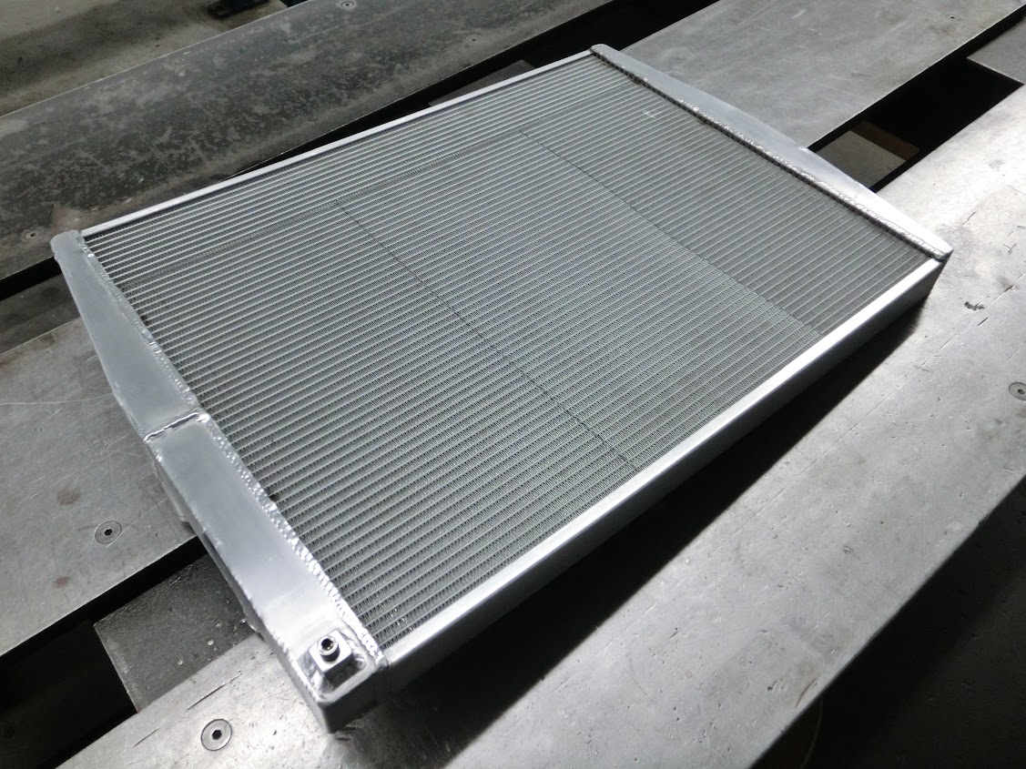
It's a 620x500x40 cooler core, to which I welded some tanks on. Maybe two of those stacked on top of each other with a big-fan on top of them will work nicely. The cores are about €175, so much more friendly on the pocket than a 50 or 60 row setrab cooler.
Ah well, just some thoughts. Lot's of stuff to consider, as usual.
Do you know how many scavange sections the MFR front cover has? I can see two scavange tubes in the pictures I've found, but can't see if there are one or two actual pump sections. I guess when going with an external setup that going for a 3-stage pump with 2 scavange sections makes sense. How do you have the oil cooler plumbed by the way? Between pressure pump and engine? I've heard of people putting the cooler between the scavange sections and the pump. Downside being that there is still air mixed with the oil at that point, so a bigger cooler is needed. Upside is that there is little to no pressure on the cooler, and less pressure loss between the pressure pump and the engine because there isn't a cooler between them. I wonder if the cooler core I used for my radiator will be suitable for an oil cooler if it's plumbed between the scavange section and tank.
It's a 620x500x40 cooler core, to which I welded some tanks on. Maybe two of those stacked on top of each other with a big-fan on top of them will work nicely. The cores are about €175, so much more friendly on the pocket than a 50 or 60 row setrab cooler.
Ah well, just some thoughts. Lot's of stuff to consider, as usual.
12-09-14, 06:33 PM
#1847
Red Pill Dealer
iTrader: (10)

I'm no race car builder, but I have some thoughts on your statement about the oil cooler going in between the dry-sump pick-up and the pump even though it has air in it.
Could the bubbles possibly collect at the top of the oil cooler limiting the actual number of rows the oil flows through? Or, would you stagger the inlet and outlet to force the air through the pump?
Cooler oil is thicker. Better for the pump to deal with or would hotter oil be?
Could the bubbles possibly collect at the top of the oil cooler limiting the actual number of rows the oil flows through? Or, would you stagger the inlet and outlet to force the air through the pump?
Cooler oil is thicker. Better for the pump to deal with or would hotter oil be?
12-09-14, 07:10 PM
#1848
I wish I was driving!
I'm no race car builder, but I have some thoughts on your statement about the oil cooler going in between the dry-sump pick-up and the pump even though it has air in it.
Could the bubbles possibly collect at the top of the oil cooler limiting the actual number of rows the oil flows through? Or, would you stagger the inlet and outlet to force the air through the pump?
Cooler oil is thicker. Better for the pump to deal with or would hotter oil be?
Could the bubbles possibly collect at the top of the oil cooler limiting the actual number of rows the oil flows through? Or, would you stagger the inlet and outlet to force the air through the pump?
Cooler oil is thicker. Better for the pump to deal with or would hotter oil be?
The scavenge section picks up oil from the bottom of the engine.
The pressure section picks up oil from the tank.
John is asking about putting plumbing the oil cooler to the outlet of the scavenge pump, then flowing to the tank, or putting the cooler on the outlet of the pressure section.
The bubbles will not collect in the cooler; they remain entrained in the oil until they reach the swirl section of the vented tank. Fluids will follow the path of least resistance, and a bubble at the top of a row would certainly be a lower resistance path than a row fully filled with fluid.
The benefit of cooling on the scavenge side of the pump as opposed to the pressure side is that there is no pressure loss by pumping through the oil coolers, so for identical engine oil pressures, the power losses are less on this set-up. However, as John mentions, the air-entrained oil is less efficient at being cooled, and as such larger coolers are required (and higher pressure rated).
John seems less concerned about maximum power than an efficient, reliable oil cooling system. If his current coolers are adequate for pressure and heat capacity, I would plumb the pressure side in his scenario.
12-09-14, 07:41 PM
#1849
I wish I was driving!
The mfr setup is a 3-stage.
See page: 29.
https://www.mazdamotorsports.com/pdf...ary_Edited.pdf
For some reason, I foresee you making your own tank...
12-09-14, 09:38 PM
#1850
Red Pill Dealer
iTrader: (10)
The flow of oil would not take that route. A dry sump pump has 3 components: a collection tank, a scavenge section, and a pressure section.
The scavenge section picks up oil from the bottom of the engine.
The pressure section picks up oil from the tank.
John is asking about putting plumbing the oil cooler to the outlet of the scavenge pump, then flowing to the tank, or putting the cooler on the outlet of the pressure section.
The bubbles will not collect in the cooler; they remain entrained in the oil until they reach the swirl section of the vented tank. Fluids will follow the path of least resistance, and a bubble at the top of a row would certainly be a lower resistance path than a row fully filled with fluid.
The benefit of cooling on the scavenge side of the pump as opposed to the pressure side is that there is no pressure loss by pumping through the oil coolers, so for identical engine oil pressures, the power losses are less on this set-up. However, as John mentions, the air-entrained oil is less efficient at being cooled, and as such larger coolers are required (and higher pressure rated).
John seems less concerned about maximum power than an efficient, reliable oil cooling system. If his current coolers are adequate for pressure and heat capacity, I would plumb the pressure side in his scenario.
Thank you.