4-Rotor FC Build
 11-10-11, 04:56 PM
#101
Whoa now I'm even more confused on how you did the exhaust. You didn't just remove the stock sleeve and use inserts. You completely bored out the housings and welded the new exhaust runners in? I can't believe that they are only press fit with epoxy around them. I'd love to see more in progress pictures of these if you've got them. I can't quite a mental picture of exactly what you did.
The gasket is a problem since they holes in the gasket are so large and extend so high above the actual port. I never really found the perfect solution but admittedly I didn't really try. If I ever revisit it again I'll look into it a bit more. A custom copper gasket may be the answer.
I remember talking to Paul Yaw about the sleeves back in the late 90's. I was inspired by an airplane engine he built that use tapered header runners that extended into the exhaust sleeve that effectively accomplished the same thing as the new sleeves. Incidentally he found a 30% increase in flow through the ports without enlarging them. Anyways, I had asked if it would be possible to use an all aluminum sleeve. He said yes as long as it was a tight press fit that would ensure good heat transfer to the housing and water passages and then suggested having the ports and runners ceramic coated just to be safe. That makes me a bit more nervous but there would be no expansion issues.
 11-10-11, 05:35 PM
#102
I'm sorry but I don't have a lot of pictures of the process. The goal was to get a perfect straight exhaust port shape without interuptions or anything. I guess I went a bit overboard and out of the box with it. 
First thing I did was mill out a perfectly round surface where the exhaust insert is going to fit in. That's picture one of the first page of this thread. In the same setup I milled out the exhaust port shape, It's milled out 2mm's larger than the final port all the way around (the thickness of the insert piece, doesnt need to be thicker because it's cooled by engine coolant). Next job was machining out the entire exhaust channel, this was done from the sides of the rotor housings.
Then I made some insert pieces out of stainless steel. The picture you can see on the first page of this thread aren't the completed inserts that are actually in the engine right now. Compare the exhaust channel shapes in different pictures, they are a bit different. I made the inserts on a manual milling machines which was difficult, so I had to make a few versions to get it how I really wanted. The final inserts actually extended to within the trochoid chamber. I marked them and made them exactly to size. The inserts were fitted into the housings, and welded together with the steel liner. Don't think about ugly mig welding, or welding it like they did here:
http://www.rotaryeng.net/Welded-steel-p-port.html
I tigged it up very slightly without adding a lot of wire or anything. I just fused the steel trochoid liner with the stainless steel insert. Afterwards everything was finished with a dremel tool. When that was all done epoxy was added inside the cooling channels. The welding should prevent coolant leaking inside the engine, and the exhaust header gasket should prevent coolant leaking outside the engine, the epoxy inside the cooling channels is just for safety and piece of mind.
The intake peripheral ports were fitted in the exact same way.
A housing was made this way, and extensively checked for warping in multiple ways. I couldn't detect any whatsoever. The chrome surface also shouldn't be affected, the heat affected zone from the welding is so extremely small, the weld was really only a few mm's wide, and was beveled. Well see how they hold up. I really tried a lot of stuff I never tried before on this engine. If I get the engine finished and running I'll probably have to tear it down after it's been running for a while and check for strange signs of wear. If these rotor housings won't work I'll swap them for more conventional rotor housings, but I can't see why they wouldn't.
 11-12-11, 05:15 PM
#106
i do think the exhaust port sleeves will cause a restriction, seeing how the stock n/a diffusers have an impact on performance. might make a setup with the exhaust manifold that retains them into the housings which will allow them to be easily removed and swapped out compared to taking the whole engine apart or living with the results.
11-13-11, 01:04 AM
#108
i do think the exhaust port sleeves will cause a restriction, seeing how the stock n/a diffusers have an impact on performance. might make a setup with the exhaust manifold that retains them into the housings which will allow them to be easily removed and swapped out compared to taking the whole engine apart or living with the results.
I've seen people say they "think" they should flow less than stock because the exit is so much smaller. The problem is that the stock exit is too large. It wasn't done this way for power. It flows as well as it's smallest part. That's the port itself. This doesn't make that smaller. The people that think these won't work as good are 100% proven wrong and have been for a very long time. They absolutely work. If more people would think this way instead of creating the largest stupidly sized ports or bridgeported aux 6 port engines (which suck!) they can, they'd get far better results. These are only going to be even more spectacular on a true race engine. Then again Mazda's own p-port housings don't have inserts and their runners are remarkably close in size to the actual exhaust port and they did that 30 years ago. They certainly don't do what the street engines do.
11-13-11, 10:59 AM
#109
Engine, Not Motor
iTrader: (1)
Join Date: Feb 2001
Location: London, Ontario, Canada
Posts: 29,789
Likes: 0
Received 108 Likes
on
91 Posts
Well, It's something I wanted to test for a while. I did a lot of flow simulation's, and I found that this sort of port doesn't increase backpressure like you would think. It does improve gas velocity however which should be good. I actually wonder if the expanding shape has something to do with the air injection system. The flow is very turbulent when it exits the rotor housing, I tried to make a straight uniform shape which should convert the turbulent flow to a laminar flow very quickly. This shape also makes it easy to create an anti reversion lip.
I also looked at the 26B exhaust inserts, they also aren't as large as you would think. This is not a turbo where you need to cram a lot of energy through the exhaust channels.
I also looked at the 26B exhaust inserts, they also aren't as large as you would think. This is not a turbo where you need to cram a lot of energy through the exhaust channels.
This may have been mentioned in the thread but I couldn't find it via searching; you center irons will be modified with an oil passage to the center bearings I assume? Will you also be modifying them for a direct coolant passage to each engine "section"?
With the dry sump, are you going to make a thick bottom plate?
11-13-11, 12:39 PM
#110
I talked about this 10 years ago! On a flowbench mine flowed nearly 30% more than stock. How is that a restriction? Why would a port that shape flow less than stock? The stock port itself is that small. It expands afterwards which creates lots of turbulence and hurts flow. This is merely keeping the port the same size it already is which speeds up exhaust flow keeping more energy in the exhaust system. This is a good thing. It helps power. It creates more of it. This technique will allow a stock sized exhaust port to flow what many ported exhaust ports flow but without the timing change.
I've seen people say they "think" they should flow less than stock because the exit is so much smaller. The problem is that the stock exit is too large. It wasn't done this way for power. It flows as well as it's smallest part. That's the port itself. This doesn't make that smaller. The people that think these won't work as good are 100% proven wrong and have been for a very long time. They absolutely work. If more people would think this way instead of creating the largest stupidly sized ports or bridgeported aux 6 port engines (which suck!) they can, they'd get far better results. These are only going to be even more spectacular on a true race engine. Then again Mazda's own p-port housings don't have inserts and their runners are remarkably close in size to the actual exhaust port and they did that 30 years ago. They certainly don't do what the street engines do.
I've seen people say they "think" they should flow less than stock because the exit is so much smaller. The problem is that the stock exit is too large. It wasn't done this way for power. It flows as well as it's smallest part. That's the port itself. This doesn't make that smaller. The people that think these won't work as good are 100% proven wrong and have been for a very long time. They absolutely work. If more people would think this way instead of creating the largest stupidly sized ports or bridgeported aux 6 port engines (which suck!) they can, they'd get far better results. These are only going to be even more spectacular on a true race engine. Then again Mazda's own p-port housings don't have inserts and their runners are remarkably close in size to the actual exhaust port and they did that 30 years ago. They certainly don't do what the street engines do.
i REALLY don't want to argue flowbench results yet again compared to an actual running combustion engine with expanding gasses...
yes it will increase velocity but this is not just air being blown through a port at a given speed.
simply removing the wings from the ports netted a 20 horsepower gain on a series 5 non turbo on the dyno. you can argue that the wings were too much of a restriction but to me it sais that the port was already too small. that was comparing a ported S5 housing with wings to a turbo housing that was not ported. not exactly the same since there is a roadblock in the middle of the port but the sides around the exit were opened up to allow it to flow more around. this was assuming mazda actually did R+D the port sleeves to serve a purpose, the purpose was to aid in torque and response but it hindered top end performance too much for my taste which is why they get yanked.
anyways my point was to make 2 port sleeves, one stock turbo port sleeve and his modified increased velocity version. being that it is going to be naturally aspirated it would be easy to swap the sleeves to see the resulting change in peak torque and horsepower curves from each. if it does work then there would easily be a market for the n/a guys to get more from their motors during rebuilds.
problem will be that the sleeves have to be nice and tight or they will itch and loosen and rattle around in the open space, eventually destroying the rotor housing and sleeve. you don't really notice it but if the sleeve comes up above the opening edge in the housing the sleeve will warp and block exhaust flow, i had one come loose and it turned into a pretzel..
but from my many years of experience with these motors and porting, if you want big numbers you need big ports. more air in and out = higher top end power curve. if you are looking for response and psuedo low end power then these ports may suit his needs, it would be better for a road course car but not for a quarter mile car.
Last edited by RotaryEvolution; 11-13-11 at 12:55 PM.
11-13-11, 04:48 PM
#111
Ah, that makes perfect sense, especially when used with a stepped header and/or expansion chamber.
This may have been mentioned in the thread but I couldn't find it via searching; you center irons will be modified with an oil passage to the center bearings I assume? Will you also be modifying them for a direct coolant passage to each engine "section"?
With the dry sump, are you going to make a thick bottom plate?
This 4-rotor is a constructed a little bit different than most 4-rotors. A 'normal' 4-rotor is a regular 2-rotor engine that has one rotor added to the front of the engine, and one rotor added to the rear of the engine. It's got 4 independent stationairy gears, and 4 main bearings.
The engine I'm building is different, it's essentially a normal 2-rotor with 2 rotors added to the front of the engine. Therefore only one center iron (the one in the middle) has to be modified. My engine is going to have 3 instead of 4 main bearings. This is why I can use a 2-piece e-shaft instead of a normal 3-piece e-shaft. Yes, the middle iron is going to have an oil passage added.
First thing I will do is modify 2 stationairy gears, and fabricate a 'coupling', which would look like this:
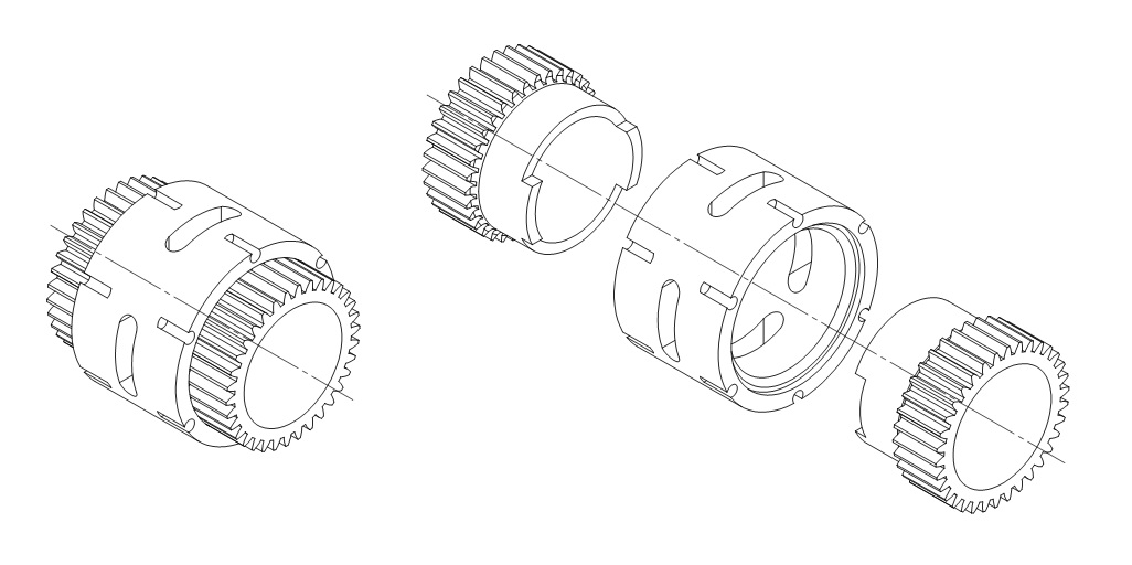
The threads are partly in the finished stationairy gears and partly in the center iron. By inserting socket screws you lock the stationary gears in the iron.
When they're in I can drill a hole in the iron where the oiling channel is going to go.
I marked it in the next picture, near the oil filler neck
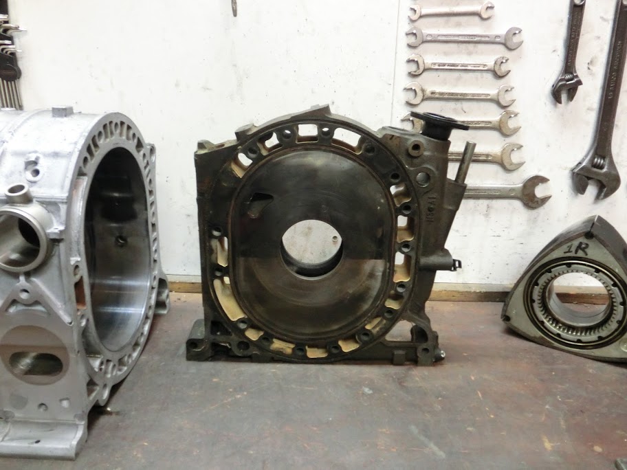
When the hole is drilled I'll insert a hollow shaft that extends into the stationairy gear. I'll probably seal it off with an o-ring or something, that's the plan anyway.
For cooling I'm planning to use the normal front in - front out setup. I am planning to place looplines that supply the rear of the engine with some cool coolant, to even out the temperature difference a bit near the exhaust channels, like they did here:
http://img.photobucket.com/albums/v2...0811152144.jpg
Waterpump is probably going to be a normal 2nd gen unit.
As for oiling I'm not going drysump. I'm planning to fabricate a oilpan, with a thick steel flange that mounts to the bottom of the engine. I haven't figured out what to do with the oilpump yet. Maybe I'll do all the oiling mods and try to get it to work with the FD pump, maybe with a different gearing ratio between the crank and the pump, to make the pump rotate at higher rpm.
 I've also thought about using an industrial oil pump that's normally used in hydraulic equipment, and then mounting it externally and driving it by an external belt that's normally used for the power steering pump. Maybe it's possible to ditch the front cover and mount a plate to the front iron, if I'm going with an external oilpump there isn't anything underneath the front cover that I need, I'm not using the OMP pump and the stock CAS. Maybe the counterweight can be added to the outside of the engine. Would make the engine a good bit shorter, waterpump will be problematic though. Lot's of food for thought here.
i REALLY don't want to argue flowbench results yet again compared to an actual running combustion engine with expanding gasses...
yes it will increase velocity but this is not just air being blown through a port at a given speed.
simply removing the wings from the ports netted a 20 horsepower gain on a series 5 non turbo on the dyno. you can argue that the wings were too much of a restriction but to me it sais that the port was already too small. that was comparing a ported S5 housing with wings to a turbo housing that was not ported. not exactly the same since there is a roadblock in the middle of the port but the sides around the exit were opened up to allow it to flow more around. this was assuming mazda actually did R+D the port sleeves to serve a purpose, the purpose was to aid in torque and response but it hindered top end performance too much for my taste which is why they get yanked.
anyways my point was to make 2 port sleeves, one stock turbo port sleeve and his modified increased velocity version. being that it is going to be naturally aspirated it would be easy to swap the sleeves to see the resulting change in peak torque and horsepower curves from each. if it does work then there would easily be a market for the n/a guys to get more from their motors during rebuilds.
problem will be that the sleeves have to be nice and tight or they will itch and loosen and rattle around in the open space, eventually destroying the rotor housing and sleeve. you don't really notice it but if the sleeve comes up above the opening edge in the housing the sleeve will warp and block exhaust flow, i had one come loose and it turned into a pretzel..
but from my many years of experience with these motors and porting, if you want big numbers you need big ports. more air in and out = higher top end power curve. if you are looking for response and psuedo low end power then these ports may suit his needs, it would be better for a road course car but not for a quarter mile car.
These are the dimensions of my intake and exhaust ports:
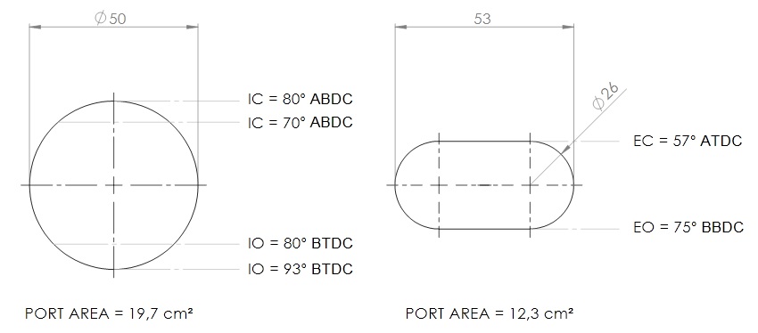
The intake and exhaust channels are the same dimensions all the way through. I didn't want to go with "bigger is always better" type of ports. Maybe top-end power would be a bit better, but everywhere else power and driveability would hurt. This engine is going in a street legal car, so I compromised.
Last edited by John Huijben; 11-13-11 at 04:51 PM.
11-13-11, 08:08 PM
#112
I would argue about these exhaust ports a bit more but I've actually done it and know firsthand how well they work so there really is no point in wasting the time. Experience wins against opinion.  Keep it up John. You'll love it! Those exhaust ports will lose no top end power at all. They only gain where the conventional type can't. All peripheral exhaust ports regardless of timing should be done this way.
Keep it up John. You'll love it! Those exhaust ports will lose no top end power at all. They only gain where the conventional type can't. All peripheral exhaust ports regardless of timing should be done this way.
11-14-11, 10:26 AM
#116
i'm just curious how you went about getting accurate results, it's obvious you don't want to discuss that though for some reason, which is probably variables.
11-14-11, 11:30 AM
#117
4th string e-armchair QB
iTrader: (11)
Join Date: May 2005
Location: North Bay, Ontario
Posts: 2,745
Likes: 0
Received 0 Likes
on
0 Posts
Seriously guys, take it to PM out of respect for John. This pissing match has no relevance to the build, he has already decided on a design for exhaust ports.
 11-15-11, 10:04 AM
#121
Engine, Not Motor
iTrader: (1)
Join Date: Feb 2001
Location: London, Ontario, Canada
Posts: 29,789
Likes: 0
Received 108 Likes
on
91 Posts
The engine I'm building is different, it's essentially a normal 2-rotor with 2 rotors added to the front of the engine. Therefore only one center iron (the one in the middle) has to be modified. My engine is going to have 3 instead of 4 main bearings. This is why I can use a 2-piece e-shaft instead of a normal 3-piece e-shaft. Yes, the middle iron is going to have an oil passage added.
First thing I will do is modify 2 stationairy gears, and fabricate a 'coupling', which would look like this:
First thing I will do is modify 2 stationairy gears, and fabricate a 'coupling', which would look like this:
 I was going to have the machine shop cut internal splines into the center hole of a center iron, then cut external splines onto a machined double ended stationary gear. The gear would have been pinned via some allen screws through the center to a support structure in the iron, then the bearing pressed in. Since my eccentric was based around 2 joined 13B shafts, it's the exact same situation. Got as far as to mocking it all up with a test shaft, but then started working on my Cosmo so all that's on the back burner for now.
For cooling I'm planning to use the normal front in - front out setup. I am planning to place looplines that supply the rear of the engine with some cool coolant, to even out the temperature difference a bit near the exhaust channels, like they did here:
http://img.photobucket.com/albums/v2...0811152144.jpg
Waterpump is probably going to be a normal 2nd gen unit.
http://img.photobucket.com/albums/v2...0811152144.jpg
Waterpump is probably going to be a normal 2nd gen unit.
As for oiling I'm not going drysump. I'm planning to fabricate a oilpan, with a thick steel flange that mounts to the bottom of the engine. I haven't figured out what to do with the oilpump yet. Maybe I'll do all the oiling mods and try to get it to work with the FD pump, maybe with a different gearing ratio between the crank and the pump, to make the pump rotate at higher rpm. I've also thought about using an industrial oil pump that's normally used in hydraulic equipment, and then mounting it externally and driving it by an external belt that's normally used for the power steering pump.
I've also thought about using an industrial oil pump that's normally used in hydraulic equipment, and then mounting it externally and driving it by an external belt that's normally used for the power steering pump.
 ) would be around 10 PSI. Since you're making an oil pan anyway, why not go with an external dry sump pump (ex-racing stuff is cheap on eBay)? The pan doesn't need to be dry so you could skip the oil tank.
11-15-11, 11:12 AM
) would be around 10 PSI. Since you're making an oil pan anyway, why not go with an external dry sump pump (ex-racing stuff is cheap on eBay)? The pan doesn't need to be dry so you could skip the oil tank.
11-15-11, 11:12 AM
#122
Granny's used the standard oil pump and had it overdriven with a custom drive gear on the oil pump. however this was a split engine and the oil did not travel the path of one engine but divided between 2 shorter shafts. not sure if this will be ideal but i think it should still be feasable.
the setup i have in mind will retain an overdriven standard turbo pump but use a dry sump plate on the bottom of the block for additional rigidity through a dry sump tank. at least that is how i have it thought up, i haven't put much thought into the external oiling system yet. the split 13B shaft design has the benefit of not having to tap the center of the block for an oil feed line, that center stat gear will actually be an oil dump location.
i also thought about what other pumps might be able to do the job, like modifying a power steering pump to pump oil versus the overpriced gear reduction units from daytona style V8's, $600 used just seems a bit steep to me. but i'm just not sure if that is possible to produce the PSI and volume necessary.
Last edited by RotaryEvolution; 11-15-11 at 11:15 AM.
11-15-11, 04:50 PM
#123
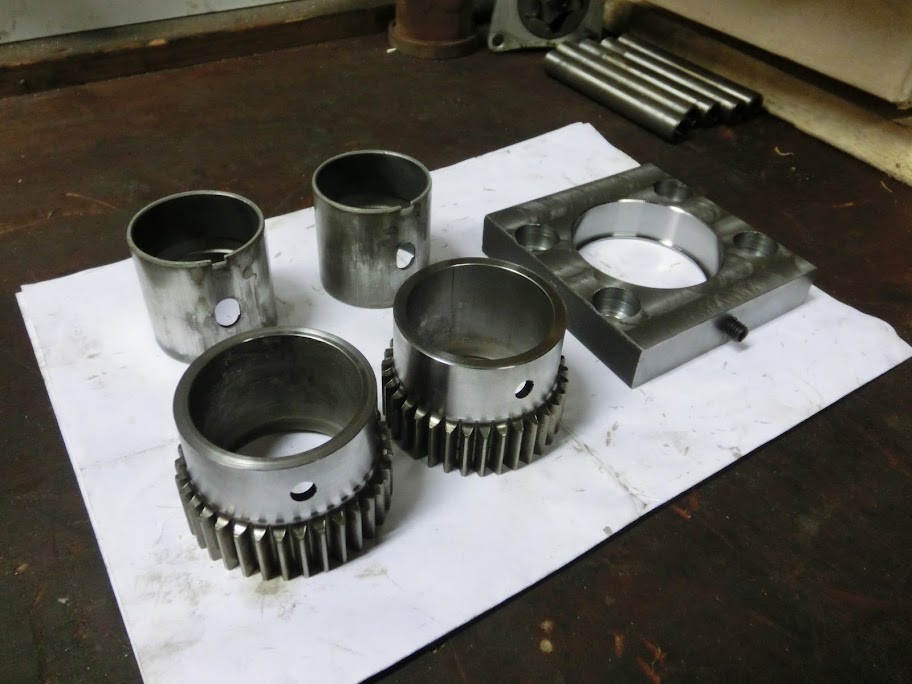
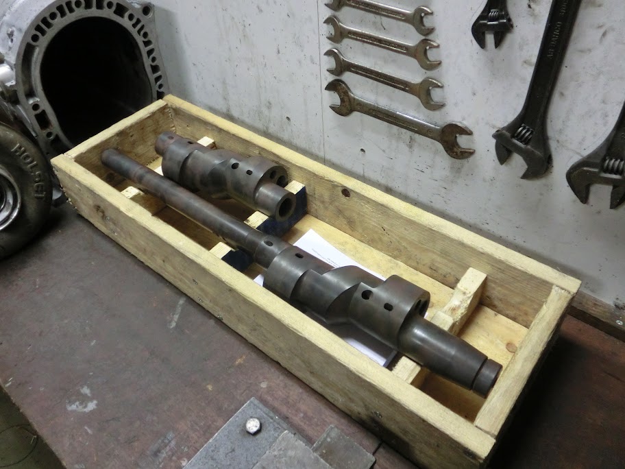
I started on the stationairy gears . Machined them down, and made a fixture to mount them in the milling machine. It's important to get the positioning of the gear tooths right, so I had to make a fixture. The allen screw is machined to fit the gear, when tightened it aligns it. Bearings will be thrown away, I'm going to have to machine 2 original bearings down to fit since the stationairy gears are machined shorter.
E-Shaft came back from it's sunny holiday at the heat treaters, got quite a tan. I thought the stress relieving would bend it a lot, but it's not that bad actually. It warped about 0,04mm's.
Yes, I saw your cosmo project a while ago, great work with all of the video's, look like it's going to be a worthy followup to the great 2nd gen 6-port turbo project log 
The stat gears would probably also work the way you described it. I went a slightly different way because it's easier for me fabrication-wise.
Electric waterpump would probably also work, but I think you'll need a BIG one to get it to flow the same as a normal S4 pump. I'm also worried about the FD oilpump, that's why I'm leaning more towards using an external oilpump with a normal sump. Those racing pumps on ebay look like an option, but I'd rather go with an industrial type pump. You can get them with about the same internals as those racing pumps, and you can choose whatever size you want. They are a bit heavier though. A buddy of mine is an hydraulic engineer, and will be doing the oily bits.
You described my oiling system wrong. The oil does not need to travel the entire length of the engine to get to the lubrication points. Look at the following picture:
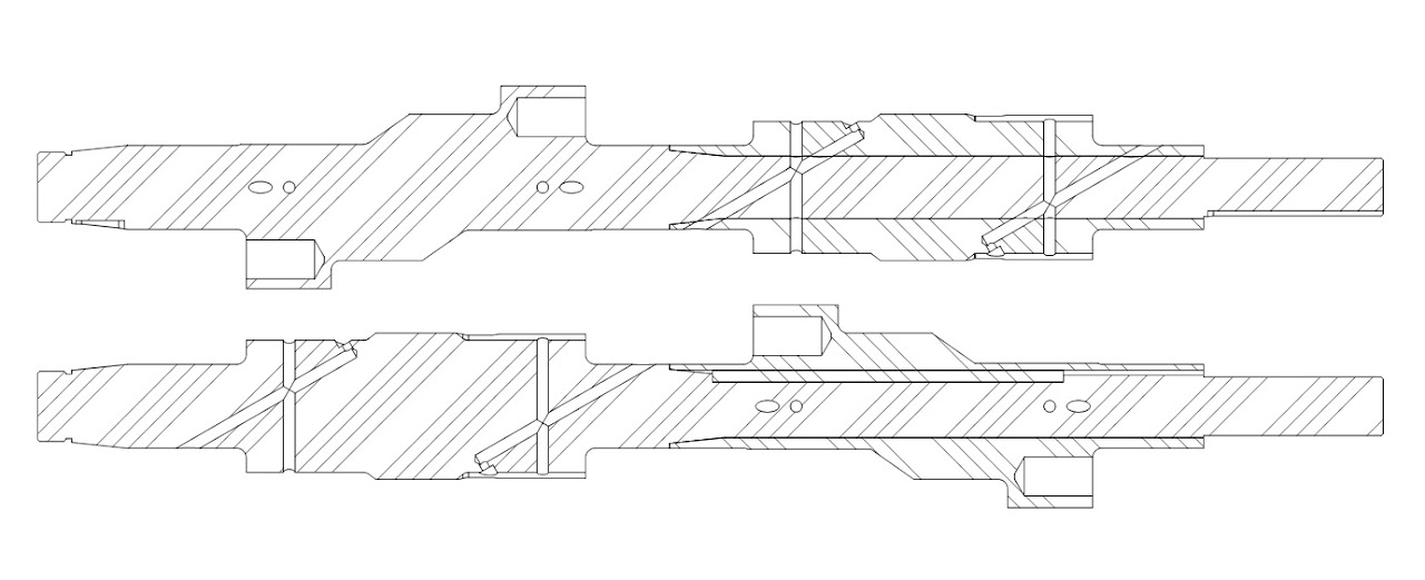
All three main bearings will have their own individual oil feeds. Distance from the oil feeds to the rotor bearings is about 3", distance to the rotor jets is about 4", It really doesn't get much shorter than this. How are you planning to use a normal oilpump with a dry sump system you need 2 pumps for that. a dry sump system doen't necessarily stiffen up the engine. You can fabricate a thick dry sump plate that stiffens up the engine, but it's also possible to fabricate a normal oilsump with a thick flange which does the same thing. Oilpan has to be custom made anyway.
. Machined them down, and made a fixture to mount them in the milling machine. It's important to get the positioning of the gear tooths right, so I had to make a fixture. The allen screw is machined to fit the gear, when tightened it aligns it. Bearings will be thrown away, I'm going to have to machine 2 original bearings down to fit since the stationairy gears are machined shorter.E-Shaft came back from it's sunny holiday at the heat treaters
, got quite a tan. I thought the stress relieving would bend it a lot, but it's not that bad actually. It warped about 0,04mm's.Wow, great minds must think alike because that's very similar to what I designed for mine. I was going to have the machine shop cut internal splines into the center hole of a center iron, then cut external splines onto a machined double ended stationary gear. The gear would have been pinned via some allen screws through the center to a support structure in the iron, then the bearing pressed in. Since my eccentric was based around 2 joined 13B shafts, it's the exact same situation. Got as far as to mocking it all up with a test shaft, but then started working on my Cosmo so all that's on the back burner for now.
Seems like a reasonable way of doing it. Basically what I had in mind as well. Nice big electric water pump with a PWM controller and no thermostat.
I'd be worried that the FD pump wouldn't supply near enough oil. Consider that with the Weber jet e-shaft mod, oil pressure on that pump will drop about 10-20 PSI at idle. Add two more rotors and I suspect idle oil pressure (idle being ~1200 RPM ) would be around 10 PSI. Since you're making an oil pan anyway, why not go with an external dry sump pump (ex-racing stuff is cheap on eBay)? The pan doesn't need to be dry so you could skip the oil tank.
I was going to have the machine shop cut internal splines into the center hole of a center iron, then cut external splines onto a machined double ended stationary gear. The gear would have been pinned via some allen screws through the center to a support structure in the iron, then the bearing pressed in. Since my eccentric was based around 2 joined 13B shafts, it's the exact same situation. Got as far as to mocking it all up with a test shaft, but then started working on my Cosmo so all that's on the back burner for now.Seems like a reasonable way of doing it. Basically what I had in mind as well. Nice big electric water pump with a PWM controller and no thermostat.
I'd be worried that the FD pump wouldn't supply near enough oil. Consider that with the Weber jet e-shaft mod, oil pressure on that pump will drop about 10-20 PSI at idle. Add two more rotors and I suspect idle oil pressure (idle being ~1200 RPM
) would be around 10 PSI. Since you're making an oil pan anyway, why not go with an external dry sump pump (ex-racing stuff is cheap on eBay)? The pan doesn't need to be dry so you could skip the oil tank.The stat gears would probably also work the way you described it. I went a slightly different way because it's easier for me fabrication-wise.
Electric waterpump would probably also work, but I think you'll need a BIG one to get it to flow the same as a normal S4 pump. I'm also worried about the FD oilpump, that's why I'm leaning more towards using an external oilpump with a normal sump. Those racing pumps on ebay look like an option, but I'd rather go with an industrial type pump. You can get them with about the same internals as those racing pumps, and you can choose whatever size you want. They are a bit heavier though. A buddy of mine is an hydraulic engineer, and will be doing the oily bits.
Granny's used the standard oil pump and had it overdriven with a custom drive gear on the oil pump. however this was a split engine and the oil did not travel the path of one engine but divided between 2 shorter shafts. not sure if this will be ideal but i think it should still be feasable.
the setup i have in mind will retain an overdriven standard turbo pump but use a dry sump plate on the bottom of the block for additional rigidity through a dry sump tank. at least that is how i have it thought up, i haven't put much thought into the external oiling system yet. the split 13B shaft design has the benefit of not having to tap the center of the block for an oil feed line, that center stat gear will actually be an oil dump location.
i also thought about what other pumps might be able to do the job, like modifying a power steering pump to pump oil versus the overpriced gear reduction units from daytona style V8's, $600 used just seems a bit steep to me. but i'm just not sure if that is possible to produce the PSI and volume necessary.
the setup i have in mind will retain an overdriven standard turbo pump but use a dry sump plate on the bottom of the block for additional rigidity through a dry sump tank. at least that is how i have it thought up, i haven't put much thought into the external oiling system yet. the split 13B shaft design has the benefit of not having to tap the center of the block for an oil feed line, that center stat gear will actually be an oil dump location.
i also thought about what other pumps might be able to do the job, like modifying a power steering pump to pump oil versus the overpriced gear reduction units from daytona style V8's, $600 used just seems a bit steep to me. but i'm just not sure if that is possible to produce the PSI and volume necessary.
All three main bearings will have their own individual oil feeds. Distance from the oil feeds to the rotor bearings is about 3", distance to the rotor jets is about 4", It really doesn't get much shorter than this. How are you planning to use a normal oilpump with a dry sump system
you need 2 pumps for that. a dry sump system doen't necessarily stiffen up the engine. You can fabricate a thick dry sump plate that stiffens up the engine, but it's also possible to fabricate a normal oilsump with a thick flange which does the same thing. Oilpan has to be custom made anyway.
11-15-11, 06:00 PM
#124
yea, i know in your setup it doesn't travel the whole length, i didn't explain it correctly if it sounded that way. main point is whether the pump, overdriven, can still provide enough oil for 4 rotors. i haven't paid attention to the 20B pump, that would be ideal if it has more volume than the 2 rotor pumps but it's tough to find info on it as there is no USDM documentation on it. my thinking is the 3 rotor supplied oil for 3 rotors plus the turbos, this should be sufficient for 4 rotors naturally aspirated IMO.