4-Rotor FC Build
 11-06-11, 02:41 PM
#76
4th string e-armchair QB
iTrader: (11)
Join Date: May 2005
Location: North Bay, Ontario
Posts: 2,745
Likes: 0
Received 0 Likes
on
0 Posts
Great build! I was thinking the reason low-pressure direct-injection (like you are describing) is not popular as a primary fuel delivery source is due to the fact that as you said, chamber pressure varies up to 3 bar on the compression stroke. This would make it very difficult to accurately inject fuel, with the delta pressure at the nozzle constantly changing, and would be very difficult to try and maintain delta. With the high-pressure direct-injection systems, they are dealing with such high nozzle pressures that a variance of 3 bar would be almost insignificant.
I think you should still try it!
I think you should still try it!
 11-06-11, 03:21 PM
#77
Did some work last weekend. The e-shaft is now ready for it's first heat treatment, so I'll see if I can get that done soon. Also sandblasted the rotor housings today because they looked horrible. Cleaned up pretty good. It was actually nice to do some simple work for a change.

Also filled in some stuff near the exhaust header flange surface. I'll mill that down soon so I'll have a nice flat surface for the exhaust header flange to mate to.
Yeah I thought about it, but I'm not going to do it. It's pretty hard to do because a dowel pin is in the way. I guess you can split the dowel pin in the middle where the extra spark plug is going to be, but I'm planning to use 2 long solid dowels from the front to the back of the engine for rigidity. It's also a lot of work to make something like that, and not really necessary.
Yeah I've thought about that, but maybe it would be best for now to take the simple way out and just use the injector setup I've already made in the housings and maybe take another look at semi direct injection in the future. I don't want this to become a never ending project. It would probably also be more effective if I spend the time it would take to build and setup injection like that elsewhere, such as a 2-step variable length intake. There are just too much cool things you can do to a rotary engine 

Also filled in some stuff near the exhaust header flange surface. I'll mill that down soon so I'll have a nice flat surface for the exhaust header flange to mate to.
it's an option, you can always cap off the ports in the housings and move them to the PP runners if the results don't wind up being what you expect. better to attempt it while the engine is apart than to try to attempt it later. but this is a big undertaking in one step, i'd at least get the 4 rotor running and see if it itself has any issues that develop first. perhaps make the inserts for both in the rotor housings and in the PP runners but start with the injectors located in the runners first.
11-06-11, 06:44 PM
#78
tell me about it, the 787B uses a system similar to that variable length intake runner system. i would suggest 2 actuators for the slide mechanism so that you don't have any binding issue, if you plan on building it that is.
Last edited by RotaryEvolution; 11-06-11 at 06:47 PM.


 11-07-11, 02:42 PM
#82
Haha, John, you're a freak 
Much more info here than on Nopistons! I Like it!
Can see that you are a better SolidWorks-guy than me
Have also thought about the variable intake.
A friend of mine have yelled at me for years to do direct injection. But I know to little about it to even try.
Keep it up John, my E-shaft is on the first grinding to connect part right now.
Will try to start on the rotors instead
11-07-11, 04:14 PM
#85

This system is used on the 89' and 90' 767B. The system I've drawn up in solidworks is a bit different mechanically, but it basically does the same thing.
Yes, good venting and not having a turbo should also help.
11-08-11, 08:36 AM
#86
Gold Wheels FTW
I had envisioned something more like a trombone slide for a variable intake. so the plenum would be fixed, and the air could be plumbed from where ever you wanted. I guess in the long run, it wouldn't matter much, and variable intake tracks are only really useful for NA application, so a fixed plenum, or a plenum at all may be a little useless. velocity stacks FTW!
[quote=John Huijben]
That sort of system is difficult to integrate into a normal front engined car chassis because there isn't room for a straight intake, and you can't make a true variable system that works for a broad enough rpm range when you use the large bends in the intake runners.[quote]
Maybe I just haven't seen a 13b in a while, but i know that on my Renesis that there's plenty of room for an extendable velocity stack.
What kind of restriction or limiting factors would a mild curve expandable intake have on the air flow into the motor? something really gradually curving over the motor that would shrink as the RPMs rise. I think it would work fine because it would become more and more efficient as RPMs rose.
11-08-11, 11:29 AM
#88
Gold Wheels FTW
did a brief amount of reading and ordered a book...
plenums are good for VE at low RPM, and trumpets are better for high RPM due to the need for shorter runners.
It would be pretty cool to have a fixed plenum intake that could be rerouted to a variable intake trumpet as RPMs rose. We'll see what my book says when it gets here...
http://www.amazon.com/Scientific-Exh...0765694&sr=8-1
11-08-11, 12:50 PM
#89
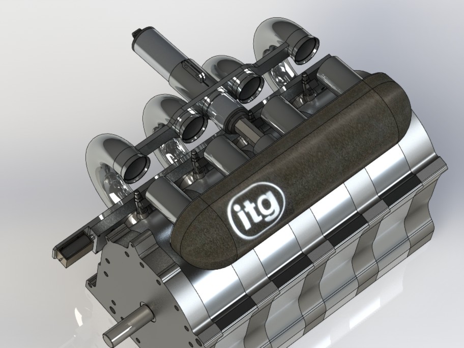
Look closely to the pictures I posted. The black air filter actually acts like a plenum. This is what's used at lower RPM's. at higher rpms the actuator extends and effectively removes the the air filter along with intake lengthening pieces from the intake system and there you have it, short intake trumpets with no plenum or filter. You'll probably find info about helmholtz resonance and how it can be used to design a plenum that boosts efficiency at a certain rpm. I calculated a plenum this way once for a friend of mine, he had a plenum made out of carbon fiber with the volume I calculated and tested it on a piston engine. It worked, even when sitting in the car you could hear when the resonating happened, and it showed on the dyno. Calculate it for a 4-rotor rotary engine though and you'll end up with a plenum that is too small to be of practical use, it was about 1,5 liters from what I can remember.
About fitting a variable intake system in a normal car. At lower rpm's lets say you would like a total intake length of about 500mm's (about 19,5"). You need some room for a plenum or filter so lets say 575mm's of total intake length. The part in the rotor housings is about 50mm, that leaves 525mm's of intake length to tuk away in the engine bay. You can't go straight out, the intake would end up where the wheel is at. You can't go up either, well without making holes in the bonnet anyway. You can't make a large bend that places the air intake area above the engine either, it would become impossible to make the intake length variable enough. If you find a way to do it though, please let me know
About fitting a variable intake system in a normal car. At lower rpm's lets say you would like a total intake length of about 500mm's (about 19,5"). You need some room for a plenum or filter so lets say 575mm's of total intake length. The part in the rotor housings is about 50mm, that leaves 525mm's of intake length to tuk away in the engine bay. You can't go straight out, the intake would end up where the wheel is at. You can't go up either, well without making holes in the bonnet anyway. You can't make a large bend that places the air intake area above the engine either, it would become impossible to make the intake length variable enough. If you find a way to do it though, please let me know
11-08-11, 01:48 PM
#90
Gold Wheels FTW
I didn't think that the break from the plenum was for that intention... very nice!
As for the adjustable intake, how much will it need to collapse ideally?
I don't think the total length detracts from what I'm thinking, but How much would a single sharp bend, and a very long slow bend effect airflow?
As for the adjustable intake, how much will it need to collapse ideally?
I don't think the total length detracts from what I'm thinking, but How much would a single sharp bend, and a very long slow bend effect airflow?
11-08-11, 02:04 PM
#91
I think a variable part that is not straight, (2 bends that fit tighly over eachother) is extremely difficult to fabricate, so I would avoid a design like that if I were you. Sharp bends aren't ideal, but look at the power they make with extremely sharp stock intake systems.
These are the intake length dimensions of the 787B engine, these lengths covered an RPM range of 6000 - 8500rpm. For street use it would be great if you can get it optimised at lower rpm, like 4500 - 8000 rpm.
787B intake lengths:
6000rpm - 585mm (23")
6500rpm - 560mm
7000rpm - 535mm
7500rpm - 485mm
8000rpm - 435mm
8500rpm - 410mm (16,1")
11-08-11, 02:47 PM
#92
Nice exhaust sleeves. I had a thread back in 2002 called "custom exhaust sleeves explained" where I showed off the exact same design that I did in one of my engines. My sleeves are one piece rather than 2 but they look the same when finished. The shape of the port is the same all the way out. They work fantastic. I still have a set of those sleeves.
EDIT: I see that my thread was linked to. The pictures are long gone on that thread but I've probably got them somewhere. It doesn't matter anyways since this shows what they look like perfectly.
EDIT: I see that my thread was linked to. The pictures are long gone on that thread but I've probably got them somewhere. It doesn't matter anyways since this shows what they look like perfectly.
11-09-11, 12:42 PM
#94
Gold Wheels FTW
11-09-11, 01:09 PM
#95
Junior Member

Join Date: Sep 2011
Location: Maryland
Posts: 13
Likes: 0
Received 0 Likes
on
0 Posts
this is simply amazing, people like you are what keep old cars like this up and going. continually pushing the envelope, and making new tech is what being an enthusiest is about... (that and loving your car  )
)
)
11-09-11, 04:37 PM
#96
the e-shaft is at the steel treatment shop, so work continues on the rotor housings.
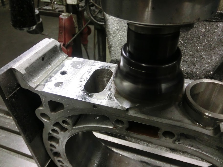


Nice and flat, had to remove about 0,05mm's.
Thanks, coming from you that means a lot. I only used 2 pieces because it was easier to fabricate it this way. The pieces were welded together before they were fitted into the rotor housings.
Nice and flat, had to remove about 0,05mm's.
Nice exhaust sleeves. I had a thread back in 2002 called "custom exhaust sleeves explained" where I showed off the exact same design that I did in one of my engines. My sleeves are one piece rather than 2 but they look the same when finished. The shape of the port is the same all the way out. They work fantastic. I still have a set of those sleeves.
EDIT: I see that my thread was linked to. The pictures are long gone on that thread but I've probably got them somewhere. It doesn't matter anyways since this shows what they look like perfectly.
EDIT: I see that my thread was linked to. The pictures are long gone on that thread but I've probably got them somewhere. It doesn't matter anyways since this shows what they look like perfectly.
Thanks, coming from you that means a lot. I only used 2 pieces because it was easier to fabricate it this way. The pieces were welded together before they were fitted into the rotor housings.
11-09-11, 08:41 PM
#98
You've taken the sleeves a step farther than I did and I like what you are doing. A problem with using sleeves with this shape is that the Mazda exhaust gasket doesn't fit up well anymore. You'll find that it actually covers the bottom corners of the ports. I just notched mine a little bit. The nice thing that you are doing is milling the surface completely flat. You can see that if it's just a insert that is installed that there is very little area from the port edges to the edge of the sleeve. This can be problematic with sealing as well.
My sleeves were made on a manual mill. They required lots of grinding by hand with a die grinder to make them fit well. The ports were machined much smaller than necessary and ground out with a die grinder. This wasn't a fun process and you have to be careful to make sure they are lined up well.
What are you using to fill those emissions passages? It looks like epoxy. I'm hoping that you threaded the holes and inserted a set screw before applying epoxy. Epoxy can't stand up to direct heat of exhaust. Incidentally I do know where to get a ceramic based epoxy that works up to 2000*F but I've never tried it.
Are you concerned about different expansion properties of aluminum vs your sleeves. I'm not too worried about 4130 steel expanding much but I'm a bit unsure about it compared to aluminum. Especially in such close tolerances. Since you've gone to this much trouble and determined what grade steel to use, I'm assuming you've already thought of this. My sleeves were held in the same way that the stock ones are except I didn't use cotter pins. I threaded the cotter pin holes in the housings and used set screws so I could remove the sleeves later if necessary. I had a custom made exhaust flange made out of 1/2" steel. I didn't use stainless because I was poor! My primary runners were 1-3/4" pipe that were carefully crushed into an oval on the end. They went straight about 3"- 4" before turning. The pipe went to 2-1/2" at the collector and even that was a bit larger than it probably could have been. Exhaust velocity is very high. Low end power is improved nicely. It will get louder due to the improved exhaust speed. I think you are going to like this setup. If I ever build another engine for myself I'm going to do the sleeves again. My current car is all stock. The engine that had the sleeves and the car it was in are long gone.
11-10-11, 12:07 AM
#99
Full Member

Join Date: Feb 2002
Location: LA
Posts: 147
Likes: 0
Received 0 Likes
on
0 Posts
These are the intake length dimensions of the 787B engine, these lengths covered an RPM range of 6000 - 8500rpm. For street use it would be great if you can get it optimised at lower rpm, like 4500 - 8000 rpm.
787B intake lengths:
6000rpm - 585mm (23")
6500rpm - 560mm
7000rpm - 535mm
7500rpm - 485mm
8000rpm - 435mm
8500rpm - 410mm (16,1")
787B intake lengths:
6000rpm - 585mm (23")
6500rpm - 560mm
7000rpm - 535mm
7500rpm - 485mm
8000rpm - 435mm
8500rpm - 410mm (16,1")
11-10-11, 04:42 PM
#100

Sourced together the iron's. The outer iron's and the middle iron are S6 FD ones. I didn't use the S4 FC n/a ones I already had, because they are weaker and have aux-ports that also have to be filled. The 2 intermediate plates are from a S4 n/a though. They have small primairy's that are easy to fill and I already had some

I think it looks pretty badass with the normal intake ports still open. Somebody needs to do a semi-pp 4-rotor
, not me though, the thought of having to fabricate a 12-runner intake system makes me cry 
You've taken the sleeves a step farther than I did and I like what you are doing. A problem with using sleeves with this shape is that the Mazda exhaust gasket doesn't fit up well anymore. You'll find that it actually covers the bottom corners of the ports. I just notched mine a little bit. The nice thing that you are doing is milling the surface completely flat. You can see that if it's just a insert that is installed that there is very little area from the port edges to the edge of the sleeve. This can be problematic with sealing as well.
My sleeves were made on a manual mill. They required lots of grinding by hand with a die grinder to make them fit well. The ports were machined much smaller than necessary and ground out with a die grinder. This wasn't a fun process and you have to be careful to make sure they are lined up well.
What are you using to fill those emissions passages? It looks like epoxy. I'm hoping that you threaded the holes and inserted a set screw before applying epoxy. Epoxy can't stand up to direct heat of exhaust. Incidentally I do know where to get a ceramic based epoxy that works up to 2000*F but I've never tried it.
Are you concerned about different expansion properties of aluminum vs your sleeves. I'm not too worried about 4130 steel expanding much but I'm a bit unsure about it compared to aluminum. Especially in such close tolerances. Since you've gone to this much trouble and determined what grade steel to use, I'm assuming you've already thought of this. My sleeves were held in the same way that the stock ones are except I didn't use cotter pins. I threaded the cotter pin holes in the housings and used set screws so I could remove the sleeves later if necessary. I had a custom made exhaust flange made out of 1/2" steel. I didn't use stainless because I was poor! My primary runners were 1-3/4" pipe that were carefully crushed into an oval on the end. They went straight about 3"- 4" before turning. The pipe went to 2-1/2" at the collector and even that was a bit larger than it probably could have been. Exhaust velocity is very high. Low end power is improved nicely. It will get louder due to the improved exhaust speed. I think you are going to like this setup. If I ever build another engine for myself I'm going to do the sleeves again. My current car is all stock. The engine that had the sleeves and the car it was in are long gone.
My sleeves were made on a manual mill. They required lots of grinding by hand with a die grinder to make them fit well. The ports were machined much smaller than necessary and ground out with a die grinder. This wasn't a fun process and you have to be careful to make sure they are lined up well.
What are you using to fill those emissions passages? It looks like epoxy. I'm hoping that you threaded the holes and inserted a set screw before applying epoxy. Epoxy can't stand up to direct heat of exhaust. Incidentally I do know where to get a ceramic based epoxy that works up to 2000*F but I've never tried it.
Are you concerned about different expansion properties of aluminum vs your sleeves. I'm not too worried about 4130 steel expanding much but I'm a bit unsure about it compared to aluminum. Especially in such close tolerances. Since you've gone to this much trouble and determined what grade steel to use, I'm assuming you've already thought of this. My sleeves were held in the same way that the stock ones are except I didn't use cotter pins. I threaded the cotter pin holes in the housings and used set screws so I could remove the sleeves later if necessary. I had a custom made exhaust flange made out of 1/2" steel. I didn't use stainless because I was poor! My primary runners were 1-3/4" pipe that were carefully crushed into an oval on the end. They went straight about 3"- 4" before turning. The pipe went to 2-1/2" at the collector and even that was a bit larger than it probably could have been. Exhaust velocity is very high. Low end power is improved nicely. It will get louder due to the improved exhaust speed. I think you are going to like this setup. If I ever build another engine for myself I'm going to do the sleeves again. My current car is all stock. The engine that had the sleeves and the car it was in are long gone.

Good point on the gasket thing, I haven't really looked into that a lot, but cutting up a stock gasket would leave an area above the exhaust channel that isn't covered by a gasket which I don't like. I don't think there are any gaskets available that I can use properly, maybe using some copper sheet, anneal it and use that for exhaust gaskets would work

The emmission passages are indeed filled with epoxy, but no worries, the hole itself is plugged with machined aluminium plugs that are a tight fit in the housings. You can see them in multiple pictures on page 1. The epoxy is just to finish everything off nicely.
I'm not worried about the different expansion rate of the stainless steel (It's regular 304 by the way). The steel has a lower thermal conductivity rate, and there isn't any exhaust sleeve inside the exhaust channel to protect it, so the steel exhaust channel would probably get hotter than the normal aluminium channel would normally get (even though the steel is continiously cooled by the cooling system). But the flipside is that steel expands far less than aluminium does, so that evens it out. I'll know for sure when the engine is up and running but I think it will be fine.
Yes sir, you are correct.