
4-Rotor FC Build


Thread Starter
Joined: Oct 2010
Posts: 605
Likes: 13
From: The Netherlands
Filled some of the ports with devcon epoxy goo. Still need to do the other side of the primairy runners because I was afraid to flip the irons over without the devcon being cured. It freezes in the garage at night, and defcon needs to cure at room temperature, so I quietly sneaked the iron's inside the house.

Also been working a lot on a side project, I've been building a chassis dyno with some friends that's now up and running. Already managed to blow up the first car that was on it. (No worries, just a 2L 16v) I'm really happy with the dyno, it's not as accurate as a dynojet but it's close, gives nice repeatable results, is capable of steady state testing, can datalog everything I can hook up to it, and can handle a lot of power. This wil really come in handy when the 4-rotor is up and running, because I can just leave the car on the dyno for a few weeks while troubleshooting and tuning everything. Really can't wait to do that.
I wish I did too, This is the first rotary engine I've ever worked on, so I'm learning as I go.
Also been working a lot on a side project, I've been building a chassis dyno with some friends that's now up and running. Already managed to blow up the first car that was on it.
(No worries, just a 2L 16v) I'm really happy with the dyno, it's not as accurate as a dynojet but it's close, gives nice repeatable results, is capable of steady state testing, can datalog everything I can hook up to it, and can handle a lot of power. This wil really come in handy when the 4-rotor is up and running, because I can just leave the car on the dyno for a few weeks while troubleshooting and tuning everything. Really can't wait to do that.I wish I did too, This is the first rotary engine I've ever worked on, so I'm learning as I go.
i'm curious about the balancing aspect, you going to put together a rotary shaft balancer? i have been looking into that (though a little on the backburner now) with a test stand and some accelerometers.
Thread Starter
Joined: Oct 2010
Posts: 605
Likes: 13
From: The Netherlands
I don't have any recent ones, I'll make some soon.
I've got an older clip of some early testing on the dyno though, Don't pay too much attention to how it looks and the crap everywhere, it's looking a LOT better at the moment. The crap is removed, and the technical parts are all covered up now.
That's my daily driver on the dyno by the way. (Yup, sloowww, but it's cheap and runs on liquid propane gas)
http://www.youtube.com/watch?v=wsPg7...5&feature=plcp
No way, I've looked into it, but that's an entire project on it's own. There aren't any shops around here that balance rotaries, so I'm thinking about fabricating my own bob-weights, assembling everything together and have it dynamically balanced at a local balancing shop. I've got the entire rotating assembly accurately modelled in the computer, and I was able to calculate the exact dimensions and position of each counterweight, so I should be able to get it very close before balancing. The front counterweight is going to be a modified S4 one. I think I'll have to make a rear one myself out of 4340 chromoly steel. I could modify a normal one by machining it down and adding a keyway (because 4-rotor counterweights are lighter than 2-rotor ones if you've got a 90deg interval) but adding a keyway and not using the original one would weaken the counterweight, and secondly, I don't have any of those counterweights.
Last edited by John Huijben; Jan 17, 2012 at 05:30 PM.

No way, I've looked into it, but that's an entire project on it's own. There aren't any shops around here that balance rotaries, so I'm thinking about fabricating my own bob-weights, assembling everything together and have it dynamically balanced at a local balancing shop. I've got the entire rotating assembly accurately modelled in the computer, and I was able to calculate the exact dimensions and position of each counterweight, so I should be able to get it very close before balancing. The front counterweight is going to be a modified S4 one. I think I'll have to make a rear one myself out of 4340 chromoly steel. I could modify a normal one by machining it down and adding a keyway (because 4-rotor counterweights are lighter than 2-rotor ones if you've got a 90deg interval) but adding a keyway and not using the original one would weaken the counterweight, and secondly, I don't have any of those counterweights.
eventually i have to worry about the same issue but i haven't figured out how much oil in the rotor they account for while the engine is running for proper balancing and that still seems to be the mystery with no feedback on the topics on the forum. the rotary balancing machine shops keep the secret to themselves, some may even improperly balance the engines i suppose.
some balancing shops claim the stock assemblies are imbalanced from the factory.
trial and error i suppose, at least the shaft should be able to take some abuse without much wear, the bearings won't be so lucky.
the weight of the oil shouldn't affect the balance all that much(since the rotors are always 180* out from one another, but in a 4 rotor it may cause more center bearing wear than a 2 rotors outer bearings) but it's still a consideration.
Last edited by RotaryEvolution; Jan 18, 2012 at 09:50 AM.

and what system did you use for the rollers? solid steel mass for the inertia or is it a mechanical brake type?
did some research into building a dyno and it doesn't seem nearly as bad as i thought, compared to spending $30k for pre-built units... just machining such a large mass is very specialized work. suppose just finding an old chassis inertia dyno and adapting it with current technology/sensors would be much simpler, can get by building your own for less than $2500. problem is most of those older dynos are lightweight(at a mere 6k lbs) and can only realistically handle 150-500whp for even the larger ones. 1000+WHP dynos are monstrous and scary thinking about that much weight rolling around down there.
did some research into building a dyno and it doesn't seem nearly as bad as i thought, compared to spending $30k for pre-built units... just machining such a large mass is very specialized work. suppose just finding an old chassis inertia dyno and adapting it with current technology/sensors would be much simpler, can get by building your own for less than $2500. problem is most of those older dynos are lightweight(at a mere 6k lbs) and can only realistically handle 150-500whp for even the larger ones. 1000+WHP dynos are monstrous and scary thinking about that much weight rolling around down there.
Last edited by RotaryEvolution; Jan 19, 2012 at 11:03 AM.
Thread Starter
Joined: Oct 2010
Posts: 605
Likes: 13
From: The Netherlands
 . You are right though, we did make that mistake once, but found out what was going on before bad things happened.
and what system did you use for the rollers? solid steel mass for the inertia or is it a mechanical brake type?
did some research into building a dyno and it doesn't seem nearly as bad as i thought, compared to spending $30k for pre-built units... just machining such a large mass is very specialized work. suppose just finding an old chassis inertia dyno and adapting it with current technology/sensors would be much simpler, can get by building your own for less than $2500. problem is most of those older dynos are lightweight(at a mere 6k lbs) and can only realistically handle 150-500whp for even the larger ones. 1000+WHP dynos are monstrous and scary thinking about that much weight rolling around down there.
did some research into building a dyno and it doesn't seem nearly as bad as i thought, compared to spending $30k for pre-built units... just machining such a large mass is very specialized work. suppose just finding an old chassis inertia dyno and adapting it with current technology/sensors would be much simpler, can get by building your own for less than $2500. problem is most of those older dynos are lightweight(at a mere 6k lbs) and can only realistically handle 150-500whp for even the larger ones. 1000+WHP dynos are monstrous and scary thinking about that much weight rolling around down there.
well it depends how complex it is to be, seems like yours is a little more complex but uses lighter moving mass. most inertia only dynos are just huge rollers with a brake and a sensor. but where to get such a huge roller, get it turned on a shaft, balanced, knurled and set into place without big equipment... that is where yours seems much simpler, of course there is no easy way to attack it as holding horsepower back requires design or sheer mass.
Last edited by RotaryEvolution; Jan 19, 2012 at 05:54 PM.

Thread Starter
Joined: Oct 2010
Posts: 605
Likes: 13
From: The Netherlands
Spended some money last week 
Bought a flywheel and clutch which should be here in a few days, and got myself a nice small alternator:

Don't need a lot of amps because I don't have a lot of creature comforts, and I wanted something small and lightweight so I bought one of a 0.8l suzuki alto, they are nice and small, and pretty easy to adapt. I'll make a bracket for it soon.
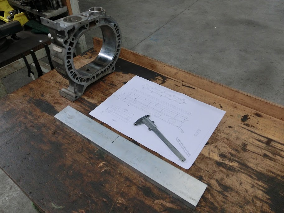
Also got some more chromoly material similar to 4140, pretty obvious what this material is going to be used for. I'm waiting on some tooling before I can finish them.

Brought the e-shaft to the grinders, which was funny and scary at the same time. They've never seen a crankshaft like this before, but I guess most people haven't. After staring at the shaft for a good half an hour with 3 guys, they figured out a battleplan on how to grind it. Long story short they're going to setup the machine with an original e-shaft, then take the original shaft out and put mine in, test-grind a rotor bearing surface and then see if they can get the dimensions within tolerance. I sure hope it's going to be okay, but if anyone can do it it's them.
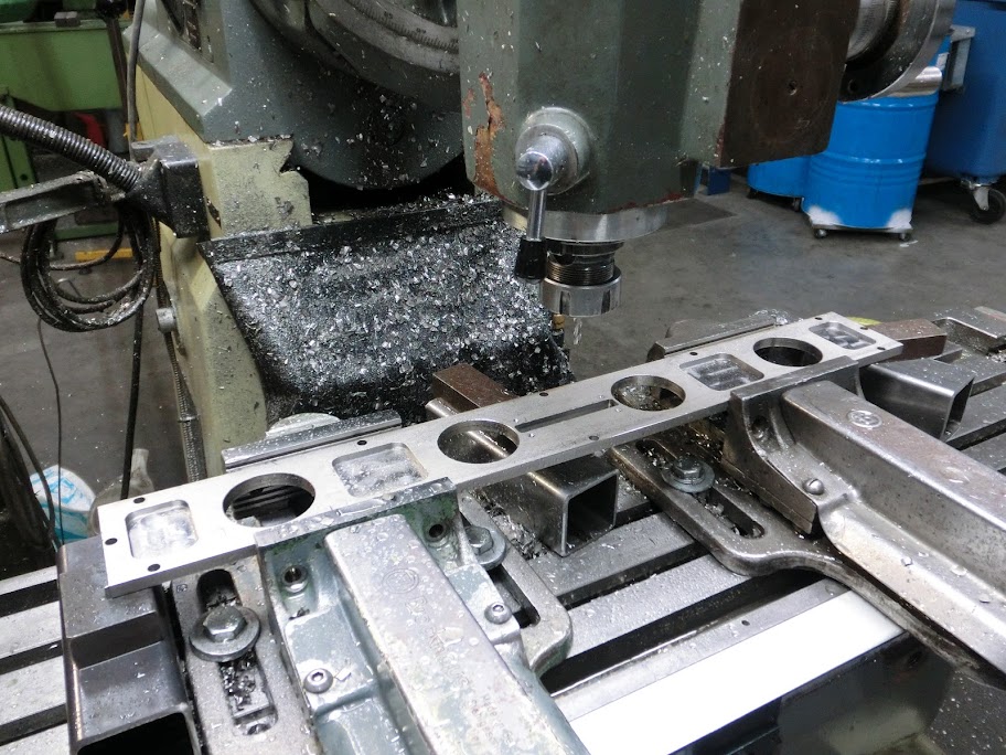
And last but not least I started on my slide throttle intake Really pleased with the progress so far. Only spended a good 3 hours or so, but it already looks expensive
Nice big slab of 6060 alloy
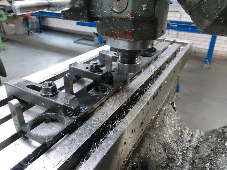
Machining one side

First side done

Machining the other side, a LOT of material needed to be removed here


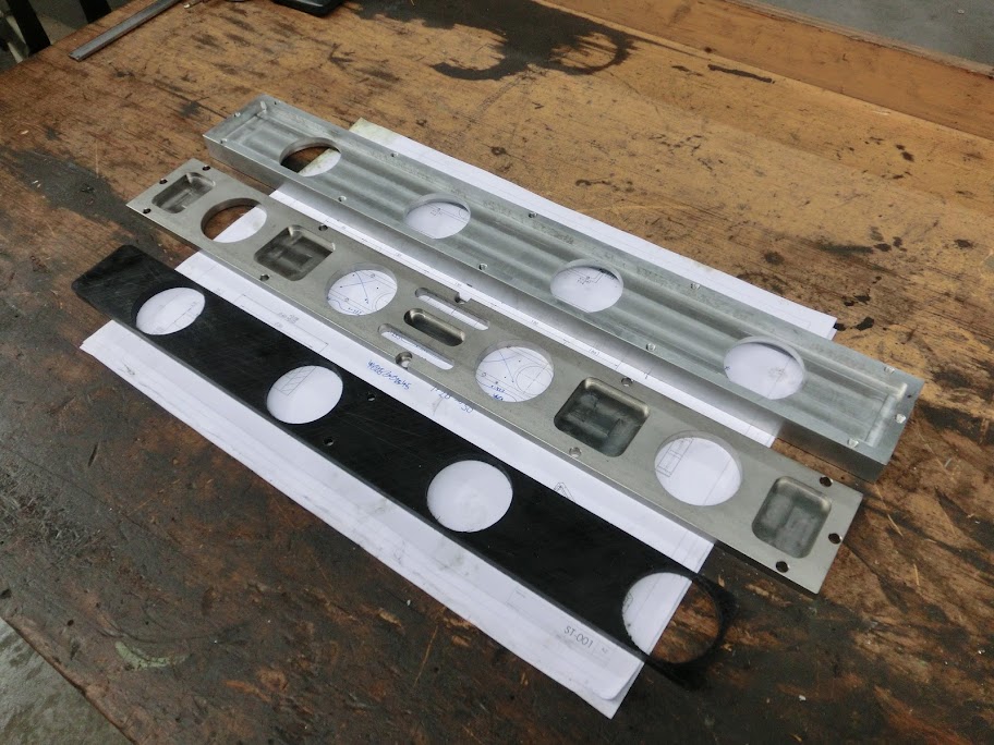
All done, the black material in the back is going to be used for the sliding plate

Bought a flywheel and clutch which should be here in a few days, and got myself a nice small alternator:
Don't need a lot of amps because I don't have a lot of creature comforts, and I wanted something small and lightweight so I bought one of a 0.8l suzuki alto, they are nice and small, and pretty easy to adapt. I'll make a bracket for it soon.
Also got some more chromoly material similar to 4140, pretty obvious what this material is going to be used for. I'm waiting on some tooling before I can finish them.
Brought the e-shaft to the grinders, which was funny and scary at the same time. They've never seen a crankshaft like this before, but I guess most people haven't. After staring at the shaft for a good half an hour with 3 guys, they figured out a battleplan on how to grind it. Long story short they're going to setup the machine with an original e-shaft, then take the original shaft out and put mine in, test-grind a rotor bearing surface and then see if they can get the dimensions within tolerance. I sure hope it's going to be okay, but if anyone can do it it's them.
And last but not least I started on my slide throttle intake
Really pleased with the progress so far. Only spended a good 3 hours or so, but it already looks expensive Nice big slab of 6060 alloy
Machining one side
First side done
Machining the other side, a LOT of material needed to be removed here
All done
, the black material in the back is going to be used for the sliding plate
Thread Starter
Joined: Oct 2010
Posts: 605
Likes: 13
From: The Netherlands
Continued with the slide throttle today, and screwed it up big time . I did the aluminium housing yesterday, and wanted to do the front cover and the sliding part today. I normally model everything in cad, but because I wanted to get it done today and I figured it was a quite simple piece anyway I went straight ahead with machining after some quick sketches. So I milled out a plate out of 304 stainless, with the same outer dimensions and holes as the aluminium housing, and since everything was going very well I even milled out some pockets, which I think look nice.

When that was done I started on the teflon sliding part that slides in the aluminium housing.
Total time spend including setting everything up was about 5 hours for both parts. I ended up with this:
Fancy looking right? I couldn't resist assembling everything together to see how everything fits. And then I noticed this:
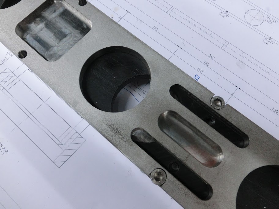
CRAP, this isn't going to work. I milled out some slots in the front plate and made some mounting holes in the sliding plate that allow me to fit a bracket onto it. The idea was to fit a bracket onto the sliding plate through the slots, so I can fit a throttle cable and returning spring. I've seen this before on multiple setups, so I didn't think too much about it. But obviously this isn't going to work. It's fine full throttle and with closed throttle, but with half throttle the #3 rotor can suck in air through this slot, causing that rotor to get more air than the other rotors, and it's unfiltered air aswell. I really don't know why I didn't think of this earlier . Anyway the front plate is scrap, already started machining a new one. I'll make the throttle cable at the top side.
On the bright side I think I figured out a clean way to incorporate a TPS sensor into the slide throttle. Normal automotive TPS sensors are rotating potentiometers that are fitted directly to the throttle valve. A sensor like that is pretty difficult to adapt to a slide throttle because my throttlevalve doesn't rotate but moves in linear direction. It's possible to make a crankshaft-like mechanism that coverts this motion allowing the use of normal sensors, but that method is bulky and not as accurate. So I looked into linear potentiometers, and found one that just might work. It's got a stroke of 60mm's, has linear resistance values (unlike audio stuff), is suited for automotive applications, is nice and small and only costs $5, so I ordered one. Since I'm re-doing the front cover anyway I'm going to try to incorporate the sensor into the front cover, which the measuring tab located into the sliding plate.
All the parts should look something like this:
(also notice the way I'm planning to do the intake runners, stainless steel tubing with delrin airhorns that can be adjusted, should make it easy to try different intake lengths)

So all and all not the most productive day, but you win some and lose some I guess.
. I did the aluminium housing yesterday, and wanted to do the front cover and the sliding part today. I normally model everything in cad, but because I wanted to get it done today and I figured it was a quite simple piece anyway I went straight ahead with machining after some quick sketches. So I milled out a plate out of 304 stainless, with the same outer dimensions and holes as the aluminium housing, and since everything was going very well I even milled out some pockets, which I think look nice. When that was done I started on the teflon sliding part that slides in the aluminium housing.
Total time spend including setting everything up was about 5 hours for both parts. I ended up with this:
Fancy looking right? I couldn't resist assembling everything together to see how everything fits. And then I noticed this:
CRAP, this isn't going to work. I milled out some slots in the front plate and made some mounting holes in the sliding plate that allow me to fit a bracket onto it. The idea was to fit a bracket onto the sliding plate through the slots, so I can fit a throttle cable and returning spring. I've seen this before on multiple setups, so I didn't think too much about it. But obviously this isn't going to work. It's fine full throttle and with closed throttle, but with half throttle the #3 rotor can suck in air through this slot, causing that rotor to get more air than the other rotors, and it's unfiltered air aswell. I really don't know why I didn't think of this earlier
. Anyway the front plate is scrap, already started machining a new one. I'll make the throttle cable at the top side.On the bright side I think I figured out a clean way to incorporate a TPS sensor into the slide throttle. Normal automotive TPS sensors are rotating potentiometers that are fitted directly to the throttle valve. A sensor like that is pretty difficult to adapt to a slide throttle because my throttlevalve doesn't rotate but moves in linear direction. It's possible to make a crankshaft-like mechanism that coverts this motion allowing the use of normal sensors, but that method is bulky and not as accurate. So I looked into linear potentiometers, and found one that just might work. It's got a stroke of 60mm's, has linear resistance values (unlike audio stuff), is suited for automotive applications, is nice and small and only costs $5, so I ordered one. Since I'm re-doing the front cover anyway I'm going to try to incorporate the sensor into the front cover, which the measuring tab located into the sliding plate.
All the parts should look something like this:
(also notice the way I'm planning to do the intake runners, stainless steel tubing with delrin airhorns that can be adjusted, should make it easy to try different intake lengths)
So all and all not the most productive day, but you win some and lose some I guess.
i would think a square slide would be a little less touchy but the slide is probably the least expensive piece to fabricate in this whole process and can be easily changed if you don't like it.

Thread Starter
Joined: Oct 2010
Posts: 605
Likes: 13
From: The Netherlands
Made another front cover
Just like before.
AISI 304 machines crappy, it can become quite nice but it takes a long time. Low spindle rpm's and lots of cooling.
What you see in this picture took 2,5 hours of manual machining
And the other side

Also made some modifications to the teflon slide and the aluminium housing
All the parts together:
Housing - Slide - Cover - Scrap
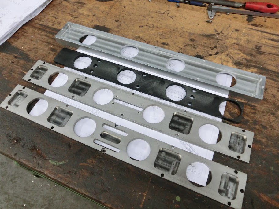
Don't worry about that slot in the middle, that's not connected to the outside world, a TPS sensor is going to live there:
That machined out part will be on the inside of the slide throttle. I'll be making a mounting plate that bolts to those 4 holes in the front cover, and those 2 holes in the sensor. This wil fix the sensor to the front cover. The lever that extends from the sensor will be located in the teflon slide. The position is already marked, I just need to make a slot in there. This way when the slide is moved and the throttle is opened the lever will move, and the sensor will tell the ecu to get some fuel into the engine
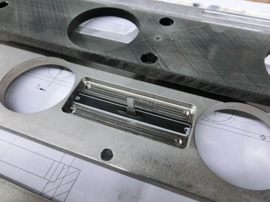
The connection to the sliding part is now moved to the top. The bolt is just for looking if the slide binds or anything, I'll see if I can machine something nice where a throttlecable and returning spring can be attached to.

Check it out:
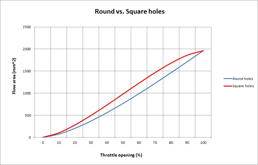
Round holes open more gently, and start opening quicker the further the throttle is opened, much like a normal throttle. The square holes open a little more agressive, and start opening slower the furter the throttle is opened, making the last 20ish percent pretty useless. I know which one I would choose
Haha, I don't think I'll be much of a competition, my chips don't taste very good, don't ask me how I know
Just like before.
AISI 304 machines crappy, it can become quite nice but it takes a long time. Low spindle rpm's and lots of cooling.
What you see in this picture took 2,5 hours of manual machining
And the other side
Also made some modifications to the teflon slide and the aluminium housing
All the parts together:
Housing - Slide - Cover - Scrap
Don't worry about that slot in the middle, that's not connected to the outside world, a TPS sensor is going to live there:
That machined out part will be on the inside of the slide throttle. I'll be making a mounting plate that bolts to those 4 holes in the front cover, and those 2 holes in the sensor. This wil fix the sensor to the front cover. The lever that extends from the sensor will be located in the teflon slide. The position is already marked, I just need to make a slot in there. This way when the slide is moved and the throttle is opened the lever will move, and the sensor will tell the ecu to get some fuel into the engine
The connection to the sliding part is now moved to the top. The bolt is just for looking if the slide binds or anything, I'll see if I can machine something nice where a throttlecable and returning spring can be attached to.
Round holes open more gently, and start opening quicker the further the throttle is opened, much like a normal throttle. The square holes open a little more agressive, and start opening slower the furter the throttle is opened, making the last 20ish percent pretty useless. I know which one I would choose
just was thinking of bikes when i mentioned it, they have used square slides for ages versus elliptical. i figured it helps make the throttle a little less sensitive in the midrange and lower end. odd that my thinking was backwards compared to your airflow chart.