SCCA Super Touring U Build


 11-22-12, 08:41 PM
#79
Updates, new Gauge Panel
Some Updates.
I have completed the installation and wiring of the main switch panels. All switches with the exception of the wipers and the dash lights are on overhead pannels. This helps keep them dry and puts them in easy reach but also away from my hands when I am racing
All of the Autometer Sport Comp gauges I had been using died so I had to replace them. Fortunately I was able to find more NOS Stewart Warner Track Force gauges for a great price - Gota Love eBay! To hold every thing I fabricated a gauge panel out of .063 aluminum. I cut the holes on a mill/drill and then put a 90 degree break on the top and bottom of the pannel for stiffness. In addtion to oil pressure, water temp, oil temp and a volt meter gauges the panel will also house a Westach dual pryrometer. The gauge panel is rubber mounted to help keep the gauges alive.
Below the guages I bult a mount for the MSD 6A ignition box. It will be rubber mounted as well.
11-23-12, 10:41 PM
#81
Thanks. The gauges had been in the car for a long time - probably since the car was built into a racecar in the mid 1990s. I'm guessing that vibrations killed them. Anyway, I tested the temp gauges using hot water and the oil temp read 20 degrees high and the water temp gauge never registered. I guess it is good idea to test your gauges every once in a while!
12-16-12, 11:50 PM
#82
Why building a racecar takes a freaking long time
Over the last several weeks I have been working on my project when time permits. During that time I have working on, of all things, a windshield defroster. A super important go fast item to be sure.
Unfortunately I am at a point in the build where I need to finish items like this before I can move forward with putting in cool stuff like gauges and ignition boxes. The defroster manifold is buried in the dash so it has to be fabbed and installed before I can continue. The problem is that it is boring work and it makes it hard to stay motivated. But the first time it rains in a race and I can see where I am going it will be worth it.
Pitures later this week
06-10-13, 05:49 PM
#83
Back from the dead
I have made some progress on this project and it is starting to reach critical mass.
- Defroster ducts added
- Gauge panels installed
- Ignition box mounted
- New steering column mount fabricated
- Brake bias adjuster mounted
- All gauge and ignition wiring completed
- Brake hard lines to the front and rear brakes completed
- -8 Fuel line from cell to the engine compartment installed
 06-25-13, 10:00 PM
#86
Current Project - New Moser Axles
When I first assembled the rear axle, I installed a set of good used Moser GSL/SE axles. However, as I started wheel shopping I learned that it is difficult to get a 15x8 with decent offset. I settled on some +15mm wheels that I liked. The issue is that they stick out to far on the car and I want to run a Hankook 225/45x15 or a Hoosier 205/50x15 tire. So I decided to get a set of shorter GSL axles made. I ordered these from RE Speed and received them promptly
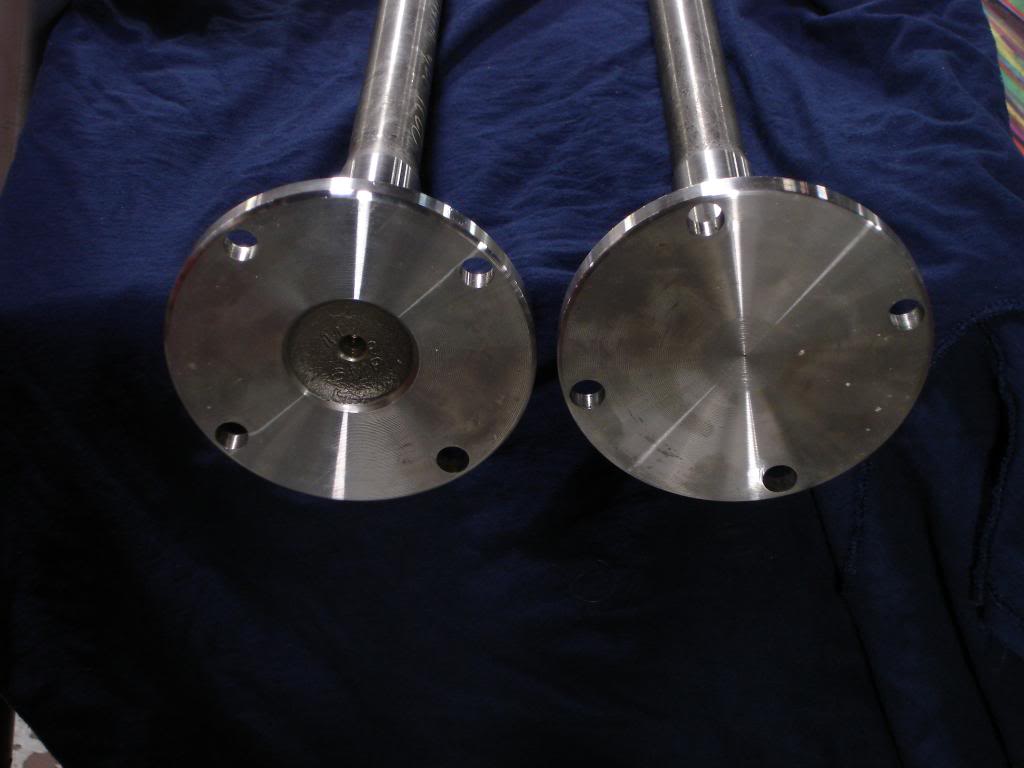
What Moser built for me is a GSL axle with a 4x114.3mm pattern. The issue is that a GSL axle has no center hub to locate either the wheel or the brake rotor. So a little custom machine work from my friends at www.santafegarage.com was in order
GSL Axles from Moser - note that they are flat
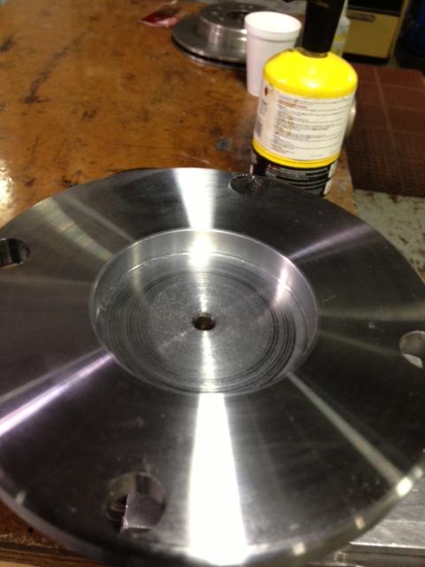
The Axles were counter bored for a hub
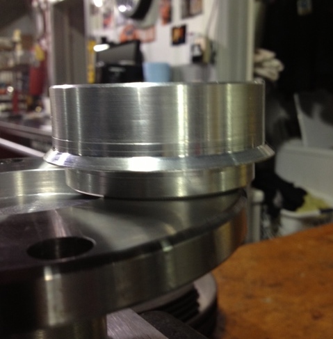
Aluminum hubs are machined to fit the counter bore and are tapered to locate the rotor. These are a press fit in the axle
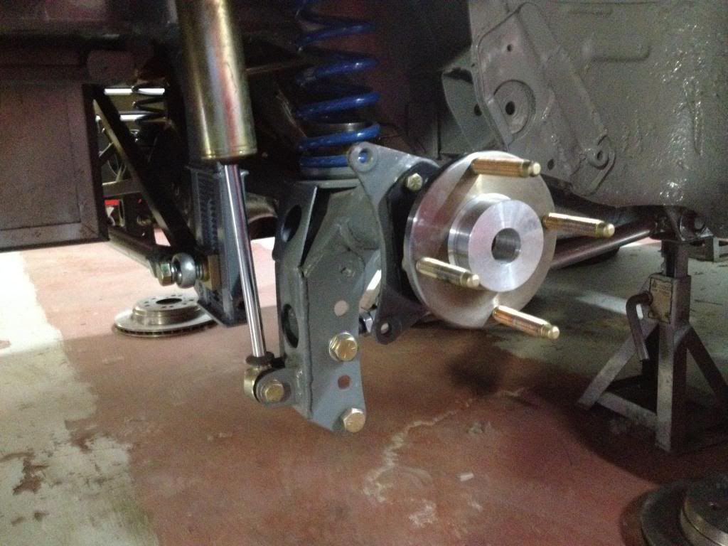
Finished product installed with ARP lug studs installed
 06-25-13, 10:12 PM
#87
Dash/Gauge Panel Installed
Just finished installing the Dash and the Gauge panel. The dash features an NOS Stewart Warner Track Force 5" memory tach, low oil pressure light and an amber shift light. The gauge panel features NOS Stewart Warner Track Force Oil Pressure, a volt meter and two water temp gauges (one of the water temp gauges will measure oil temps). In addition is a Westach dual pyrometer and a Summit Racing RPM switch. The gauge panel is rubber mounted to help the gauges stay alive and all of the gauges a lighted. Below the gauge panel I have installed an MSD 6A that also rubber mounted
To the right of the gauge panel I have a CNC brake bias adjuster mounted to the cage. The new steering column mount can be seen to the left, It clamps to the dash bar behind the tach and uses a Rod End Supply .75" steering column hiem. I had David Long at www.santafegarage.com machine a brass bushing so that the stock steering shaft would fit snuggly in the hiem The quick disconnect hex is roll pinned to the steering shaft so it can be removed.
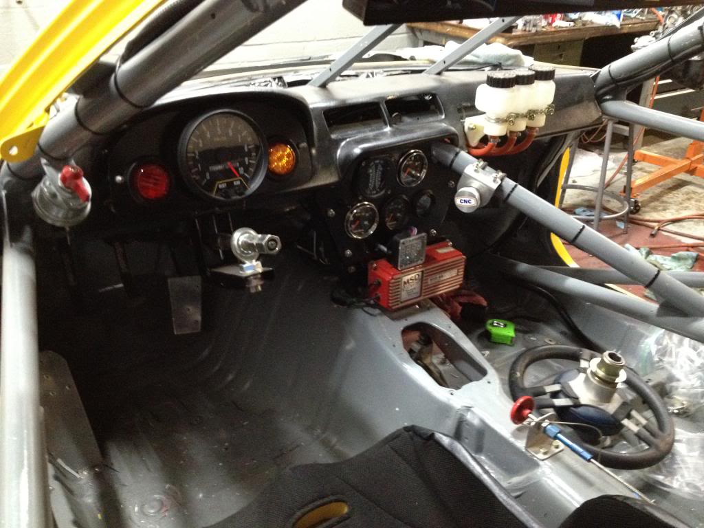
To the right of the gauge panel I have a CNC brake bias adjuster mounted to the cage. The new steering column mount can be seen to the left, It clamps to the dash bar behind the tach and uses a Rod End Supply .75" steering column hiem. I had David Long at www.santafegarage.com machine a brass bushing so that the stock steering shaft would fit snuggly in the hiem The quick disconnect hex is roll pinned to the steering shaft so it can be removed.


 06-27-13, 09:34 PM
#91
Front Suspension
Strut tops were raised 1 inch. I left the original tops in place so I could reference the 4 strut mount holes while I welded the new tops on. I later used a plasma cutter to remove the original strut tops.
Then I cut away the inner fenders and the box structure behind the strut towers for tire clearance. This really was a sucky PITA job. What I cut out of the box structure I had to weld back in
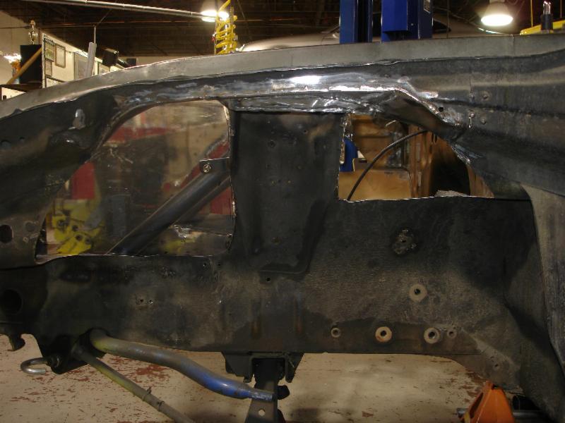
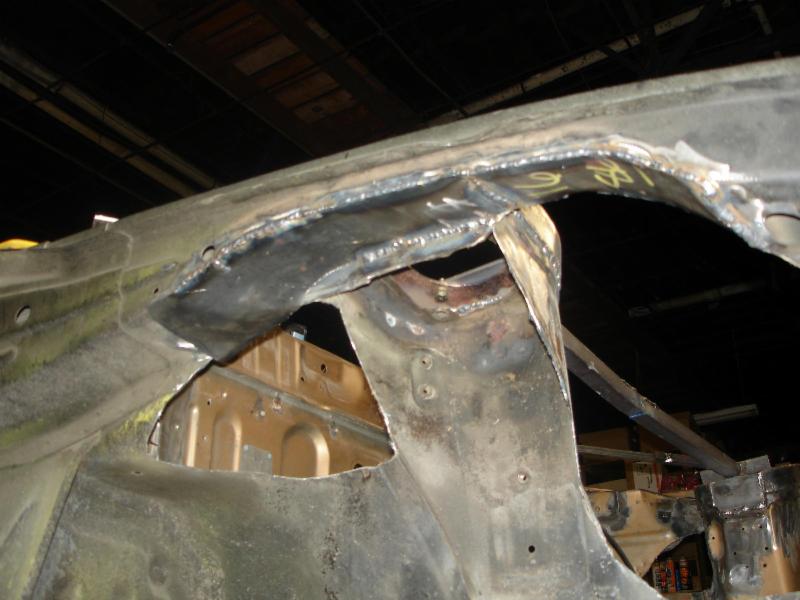


Then I cut away the inner fenders and the box structure behind the strut towers for tire clearance. This really was a sucky PITA job. What I cut out of the box structure I had to weld back in

 06-27-13, 09:56 PM
#92
More Front Suspension
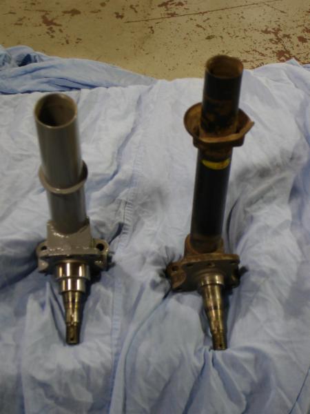
The 84-85 spindles had the stock tubes cut out and then the spindle was bored out to accept 2" strut tubes so that Koni strut inserts can be used. I had these on the car when I raced it in IT. I cleaned them up and had them checked for cracks before I made and new modifications.
Comparison between stock and the big tube struts
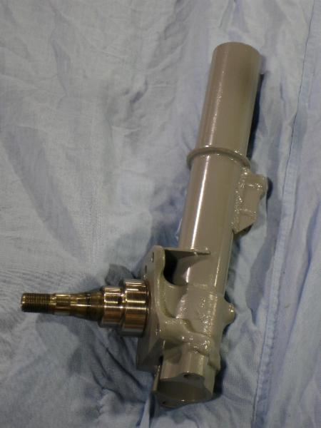
A sway bar mount was added to the strut tube. The steering knuckle mounting holes were drilled out to accept 1/2 bolts and were spot faced. The RE Speed big brake bearing adapters are installed in this photo.
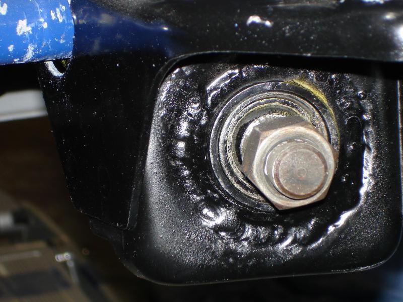
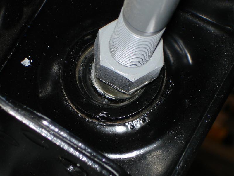
Tension Rod mounts
Here are the spherical bearing mounts on the chassis. Bearing cups were welded on to hold the Aurora .75 Spherical bearings
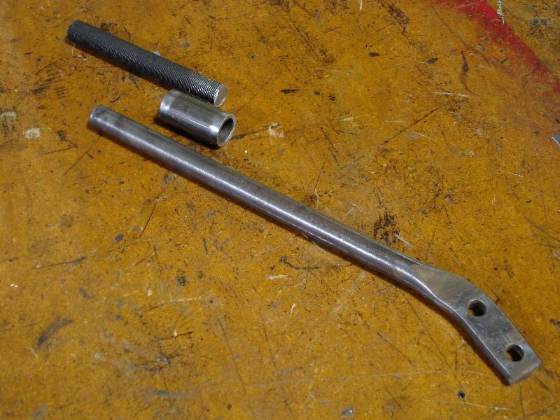
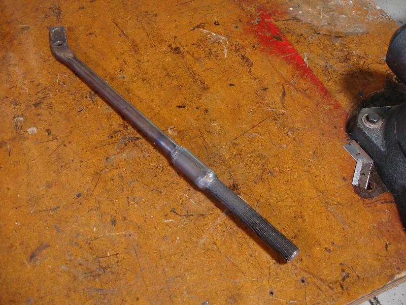
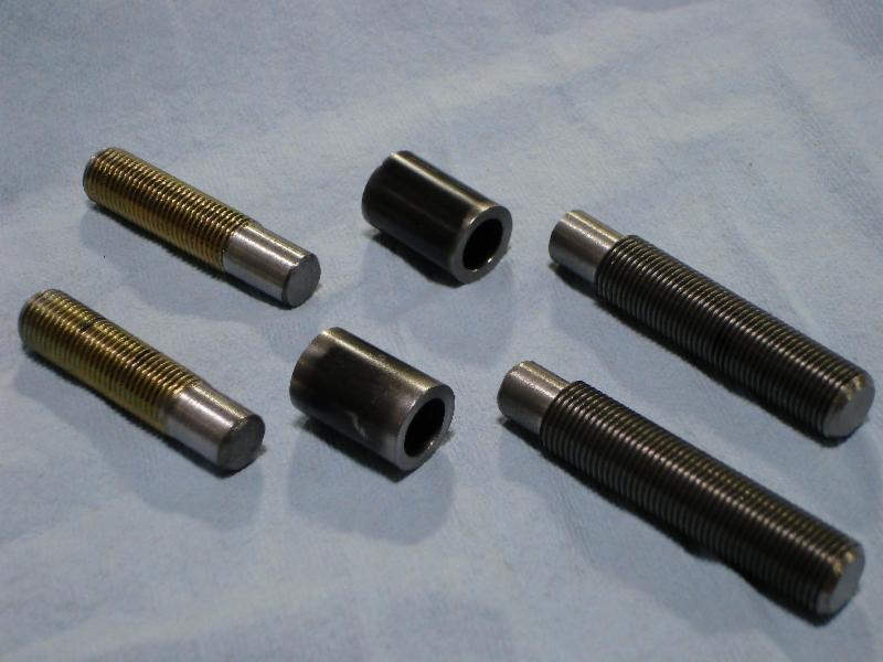
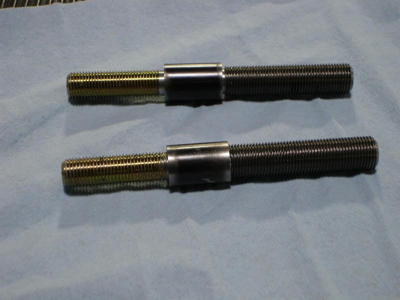
The tension rods were modified to fit the .75 spherical bearings in the mounts. Stock tension rods were shortened and hardened all thread from McMaster Karr was sleeved and welded on
Comparison between stock and the big tube struts

A sway bar mount was added to the strut tube. The steering knuckle mounting holes were drilled out to accept 1/2 bolts and were spot faced. The RE Speed big brake bearing adapters are installed in this photo.

Tension Rod mounts
Here are the spherical bearing mounts on the chassis. Bearing cups were welded on to hold the Aurora .75 Spherical bearings


The tension rods were modified to fit the .75 spherical bearings in the mounts. Stock tension rods were shortened and hardened all thread from McMaster Karr was sleeved and welded on

 06-27-13, 10:06 PM
#93
Even More - Bump Steer Correction
In place of the stock outer tie rod ends I fitted 5/8" female rod ends. I had to build new adjusters to adapt the metric inner tie rod to the SAE rod ends
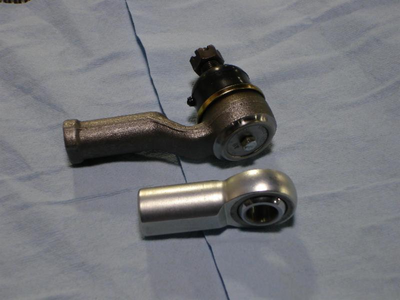
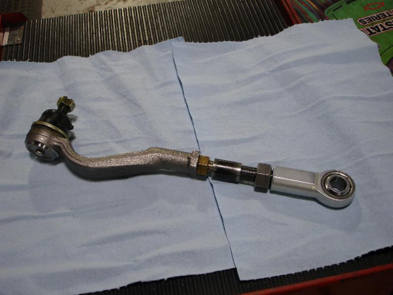
Note that the stock outer tie rod end is angled. The steering arm was heated and bent to make up for the fact that the rod end is not angled.
Stock Arms
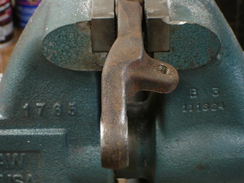
Modified
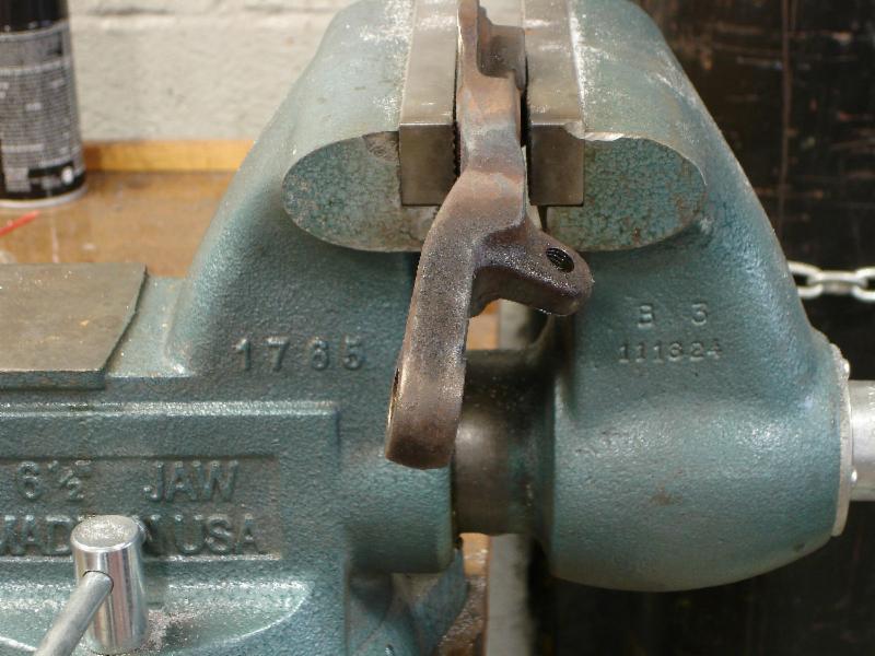


Note that the stock outer tie rod end is angled. The steering arm was heated and bent to make up for the fact that the rod end is not angled.
Stock Arms

Modified


 07-05-13, 09:37 PM
#95
Rear Suspension
The stock 4 link/Watts link was abandoned many years ago on this car. When I purchased it had a modified G Force Tri-Link and pan hard bar. It worked well and I raced the car like that for 7 years.
When I say the Tri Link worked well, it did for a car with Improved Touring power (about 125 at the crank). However my E Production friends found that with double the horse power the Tri Link is found wanting. The issue was that the drivers could get the cars off a corner without wheel spin. EP Miatas were killing them.
The problem is that body mount on the G Force Tri Link is not mounted high enough so the rear suspension doesn't have the right geometry. In Improved Touring and E Production it is hard to solve this issue because of the way the rules are written. I, on the other hand, am building an STU cars and the rules are different.
My Three Link has three equal length trailing arms. One on top and two on the bottom. All of the arms are adjustable for squat/anti-squat and for pinion angle. To locate the axle side to side I am using a pan-hard rod.
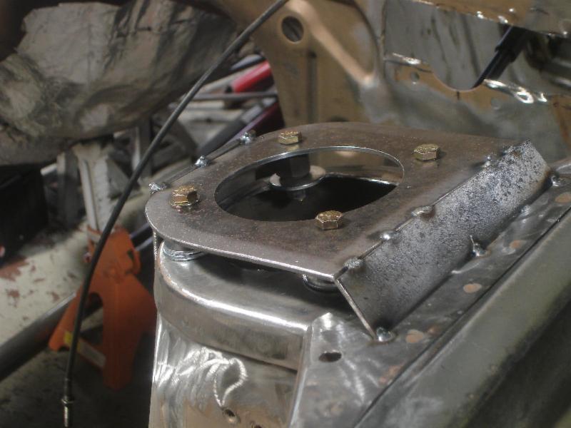
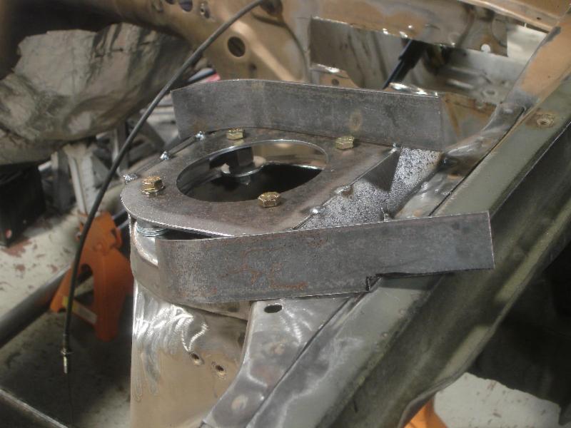
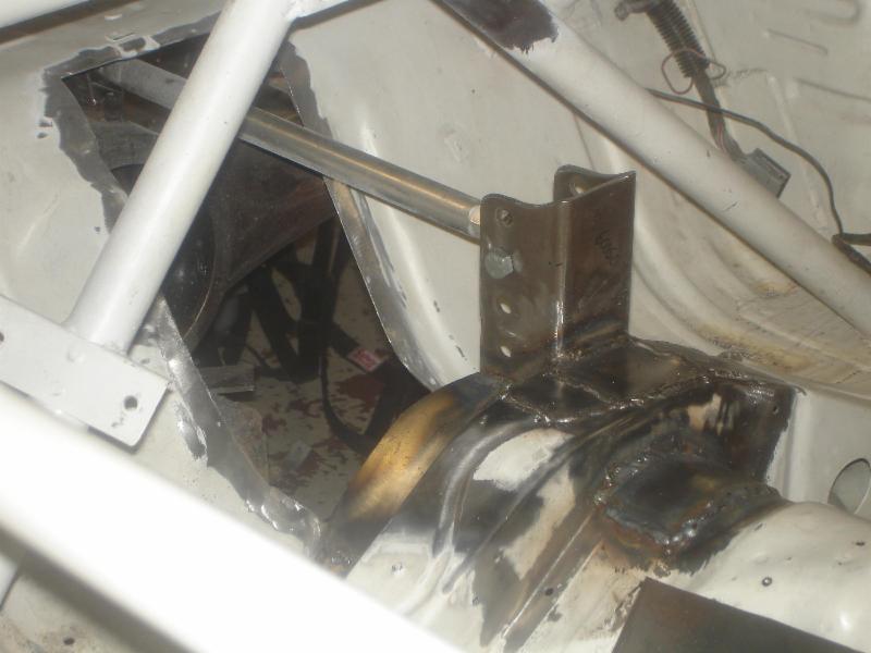
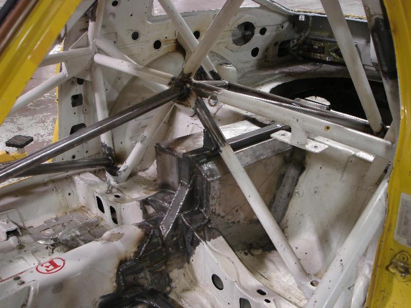
Third link mount in the car. This was later modified heavily and integrated into the cover for strength. The arm is extruded aluminum with LH and RH 5/8 threads. The rod ends are Aurora 5/8 with 1/2 holes. These can be purchased from Coleman Machine in various lengths.
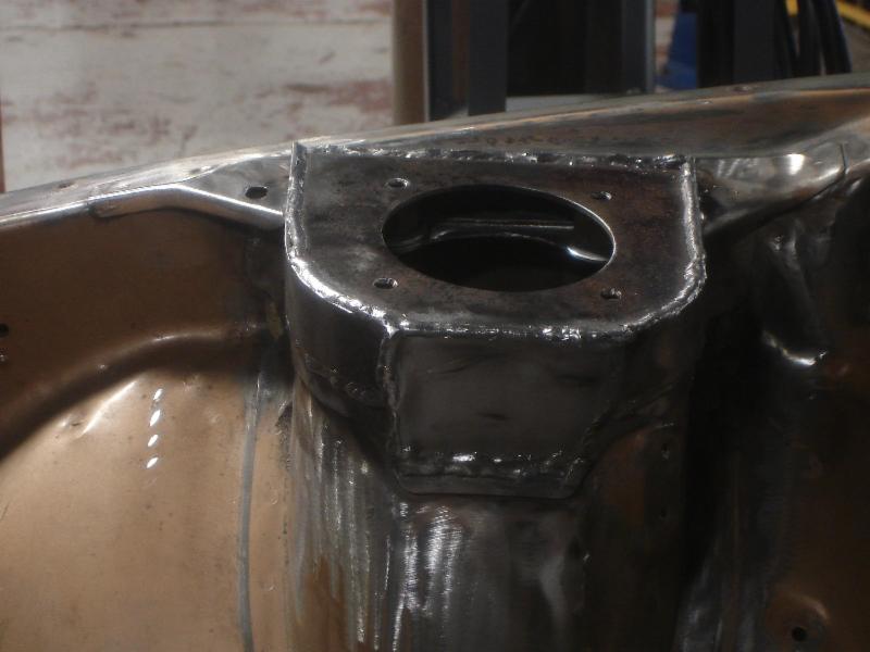
The cover was fabricated out of 18ga steel. It is welded to the car and sealed to provide a fire barrier. Later this was attacked to the cage for more strength
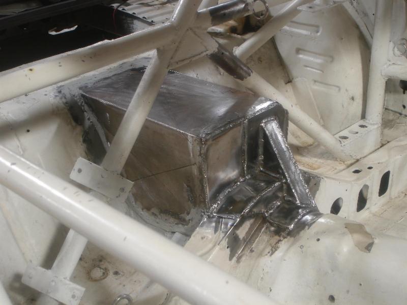
Here is a shot of the cover integrated into the cage
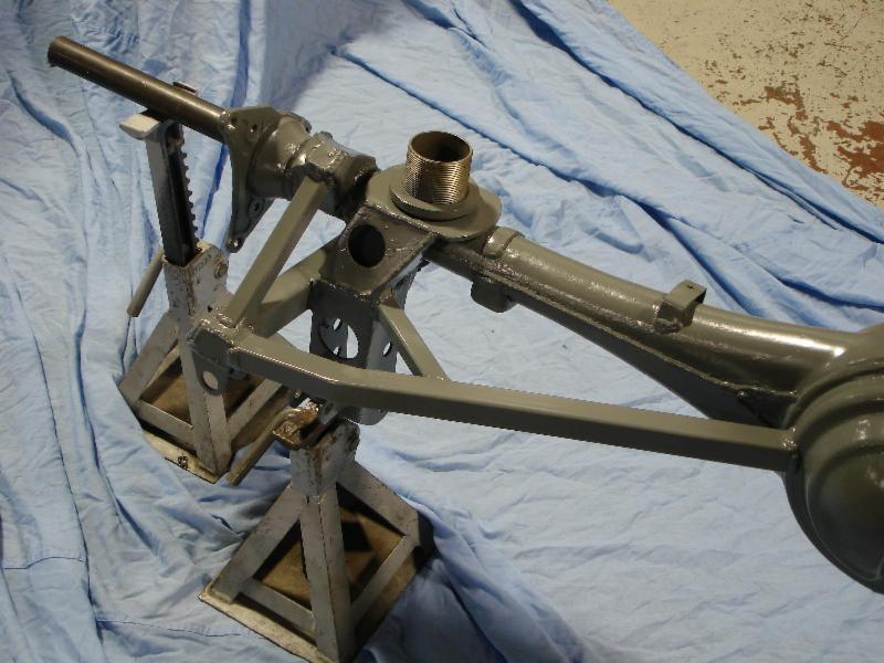
Third link mount on the axle housing. Off set to the left so that the drive shaft isn't in the way when making adjustments under the car. All of the adjustments are on the chassis for squat/anti-squat
When I say the Tri Link worked well, it did for a car with Improved Touring power (about 125 at the crank). However my E Production friends found that with double the horse power the Tri Link is found wanting. The issue was that the drivers could get the cars off a corner without wheel spin. EP Miatas were killing them.
The problem is that body mount on the G Force Tri Link is not mounted high enough so the rear suspension doesn't have the right geometry. In Improved Touring and E Production it is hard to solve this issue because of the way the rules are written. I, on the other hand, am building an STU cars and the rules are different.
My Three Link has three equal length trailing arms. One on top and two on the bottom. All of the arms are adjustable for squat/anti-squat and for pinion angle. To locate the axle side to side I am using a pan-hard rod.
Third link mount in the car. This was later modified heavily and integrated into the cover for strength. The arm is extruded aluminum with LH and RH 5/8 threads. The rod ends are Aurora 5/8 with 1/2 holes. These can be purchased from Coleman Machine in various lengths.

The cover was fabricated out of 18ga steel. It is welded to the car and sealed to provide a fire barrier. Later this was attacked to the cage for more strength

Here is a shot of the cover integrated into the cage

Third link mount on the axle housing. Off set to the left so that the drive shaft isn't in the way when making adjustments under the car. All of the adjustments are on the chassis for squat/anti-squat
 07-05-13, 09:58 PM
#96
More Rear Suspension
A big bearing rear axles from an 84-85 RX7 was heavily modified. The lower control arm mounts were changed to allow for adjustment and to allow the rear axle to be raised in the car while maintaining desired geometry. I used pre-drill control arm mounts from All Star Racing.
The lower control arms are also extruded aluminum with 5/8 Aurora rod ends. The rod ends on the chassis were bushed so that the OE 14mm bolts could be used. The factory mounting location for the lower control arms was also used.
The rear axles was also modified for the use of a panhard bar.
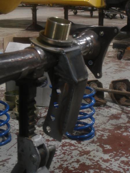
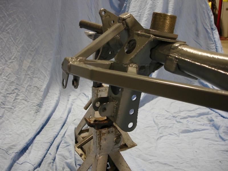
Right side lower control arm mount welded on. Also the adjustable spring mounts for the 2.5" coil over springs can be seen
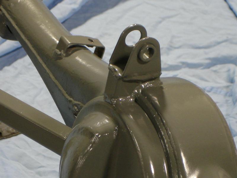
Panhard bar mount on the left side
More on the panhard mount
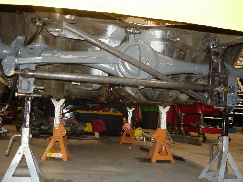
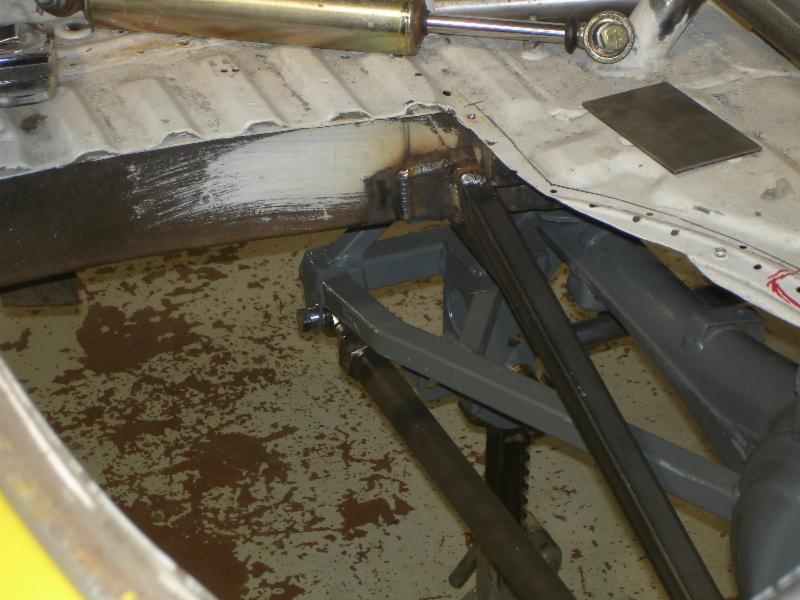
In the car from the rear. You can see the adjustable pan hard rod mount on the right side of the chassis. Later I added a cross member to tie the chassis mounting locations of the panhard rod.
From inside the car
The lower control arms are also extruded aluminum with 5/8 Aurora rod ends. The rod ends on the chassis were bushed so that the OE 14mm bolts could be used. The factory mounting location for the lower control arms was also used.
The rear axles was also modified for the use of a panhard bar.
Right side lower control arm mount welded on. Also the adjustable spring mounts for the 2.5" coil over springs can be seen

Panhard bar mount on the left side

More on the panhard mount

In the car from the rear. You can see the adjustable pan hard rod mount on the right side of the chassis. Later I added a cross member to tie the chassis mounting locations of the panhard rod.

From inside the car
 08-05-13, 09:34 PM
#100
New Project - Rear Brakes
One of the foundations of the build is the ability to use FC turbo brakes on an FB. On the front I used the RE Speed kit but never got around to buying the adapter parts for the rear. I decided to make my own....after all, how hard could it be?? Well the answer is not real hard but it was time consuming as it took around 12 hours to design and make them.
I started with two 3/16" pieces of hot roll steel that were about 7 1/2" x 2 1/2". This is what I ended up with
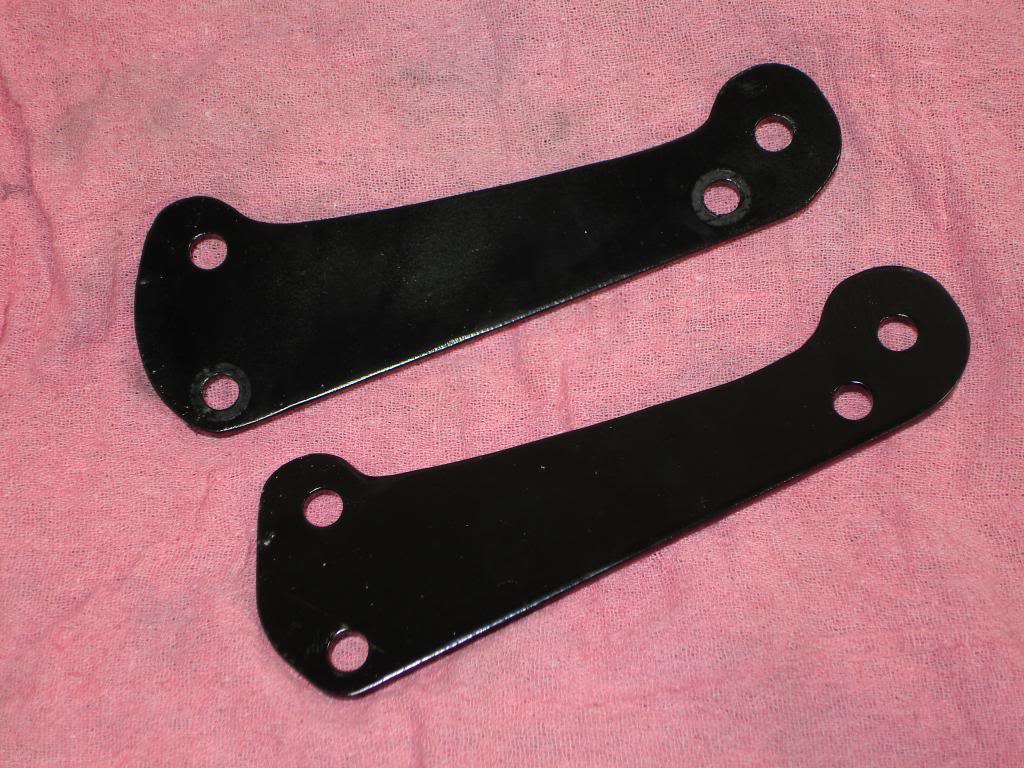
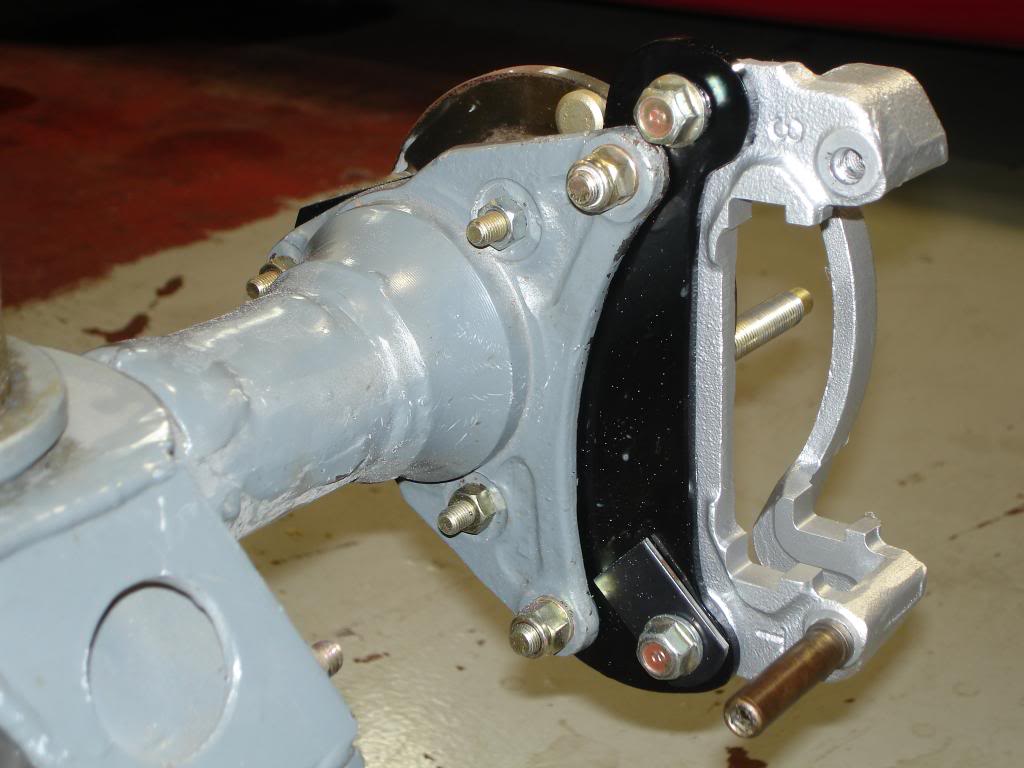
The brackets are designed to "clock" the calipers up from the OE caliper mounts. This was done to help with fitting the calipers around the panhard mount that is on the left side of the axle housing. This did require the factory brackets to be notched. See below
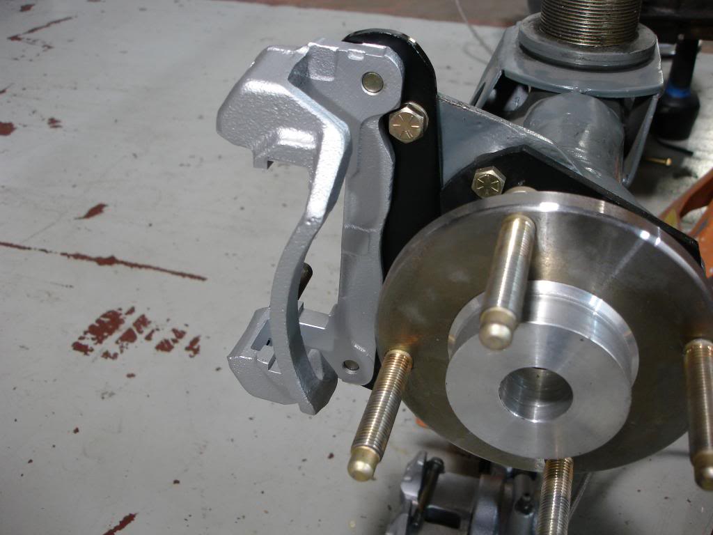
Here are images of the adapter bracket bolted on with the OE caliper bracket fitted.
Left side
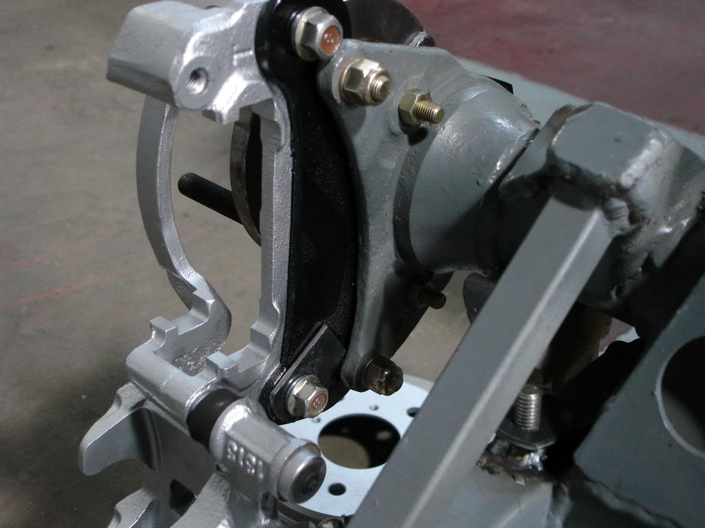
Right side
I started with two 3/16" pieces of hot roll steel that were about 7 1/2" x 2 1/2". This is what I ended up with

The brackets are designed to "clock" the calipers up from the OE caliper mounts. This was done to help with fitting the calipers around the panhard mount that is on the left side of the axle housing. This did require the factory brackets to be notched. See below

Here are images of the adapter bracket bolted on with the OE caliper bracket fitted.
Left side

Right side
