When you click on links to various merchants on this site and make a purchase, this can result in this site earning a commission. Affiliate programs and affiliations include, but are not limited to, the eBay Partner Network.
In OE configuration, air is continuously �fed� to the waste gate (WG) actuator chamber from the compressor. The OE 2-port solenoid valve is installed on a separate �bleed� line from the WG actuator, vented to the atmosphere. The OE solenoid valve is controlled by the OE ECU. If the ECU is replaced by a PowerFC, the logic and configuration don�t change. However, the PowerFC allows you to set your own boost target and solenoid duty cycle. The latter appears to be the most critical parameter. This is the �initial� duty cycle of the bleed valve after transition. Higher duties cause more air to bleed from the WG actuator, and � as a result � more boost.
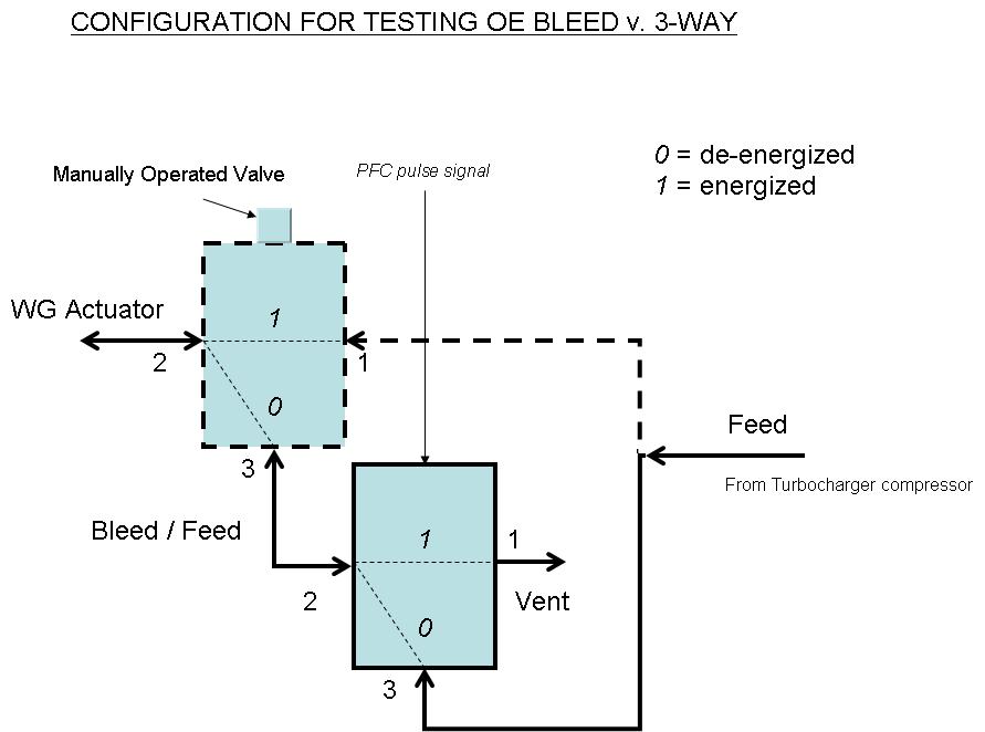
EBCs use instead a 3-port solenoid valve. The valve is installed between the compressor and the WG actuator chamber. One of the ports (common) is always open and is connected to the actuator chamber, a second port is connected to the compressor (feed) and the third one (bleed) vents to the atmosphere. With the solenoid de-energized, the feed port is open and the bleed port is closed � which is fail-safe. When the solenoid is energized the vent port opens and the feed port closes at the same time, �blocking� the feed from the compressor. Because of this, the �gain� of a 3-port �EBC� style configuration is higher than the OE configuration, where only the bleed valve cycles while the actuator is always fed by the compressor. With a 3-port valve, there is no more use for the OE bleed line, and this is why you cap off the redundant actuator nipple, when you install an EBC.
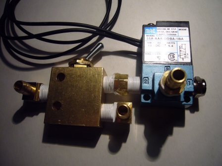
My rig consists of MAC valve coupled to a 3-port toggle operated manual valve
The two valves are plumbed as indicated below
The dotted feed line is the OE line with the pill inside
This is how they look together
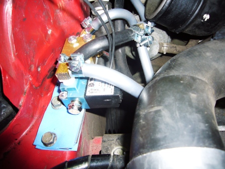
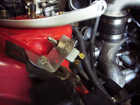
And this is how they look installed and plumbed
I also installed a three position DPDT switch
To direct the PowerFC signal either to the OE solenoid or to the MAC solenoid.
note that 3 port solenoids are what come with every major external EBC (Greddy etc). they can be used for single turbo, non sequential twins, or sequential twins.
FYI I would make part 2 or 3 something really straight forward and accessible with a title like "Write UP: increasing sequential spool with Power FC and cheap upgraded boost control solenoids" or something like that. It would be targetted towards people who don't know or don't care about all the different types of configurations and just want something that "works." Only two or three sentences would be necessary explaining the theory, like "instead of bleeding air out of the actuator like the factory solenoids, this blocks the wastegate signal just like a Greddy Profec"
Car has DP, MP, Apexi N1 Dual, stock twin with un-ported WG, and PowerFC
Row P20 in the PFC is scaled to pull timing advance to 0 deg when boost hits 1.00 Kg/cm2, as �safety row�. With the stock control system, I had found the �right� combination of settings (boost and duties) to run at 13-14 psi during autox (2nd gear only and short straights). However, occasionally the safety row gets hit under full throttle at high rpm (in the vicinity of 8000).
The reason I got initially interested in the MAC valves was to see if I could possibly avoid hitting the safety row. I expected that a configuration using 3-port valves would react faster than the OE configuration and possibly stop boost creep. My hypothesis was that my boost creep was not necessarily due to the mechanical limitation of the internal, un-ported WG, but rather to limitations of the OE bleed control.
To prove or disprove it, my first test was to exclude any WG valve control and let the WG open just as a result of the pressure build up in the actuator chamber. With the electrical switch toggle in the �N� position, no signals are sent to the solenoids. With the solenoids de-energized, the bleed valve (OE valve) is closed and the feed valve (MAC) is open. Through the air valve, I also excluded the feed line with the pill. The WG actuator chamber would receive full boost from the compressor with no delay. This is the resulting log of a 2nd gear pull at full throttle.
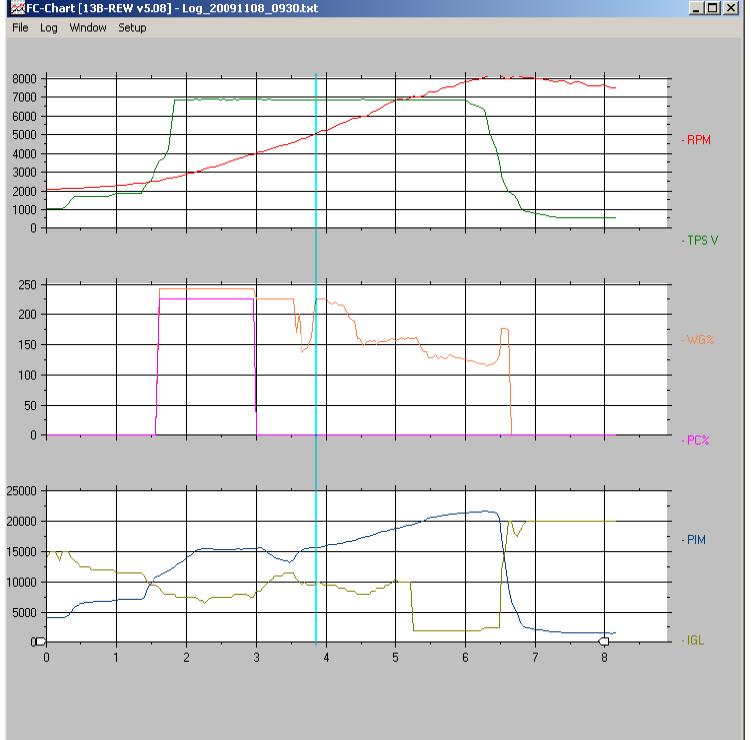
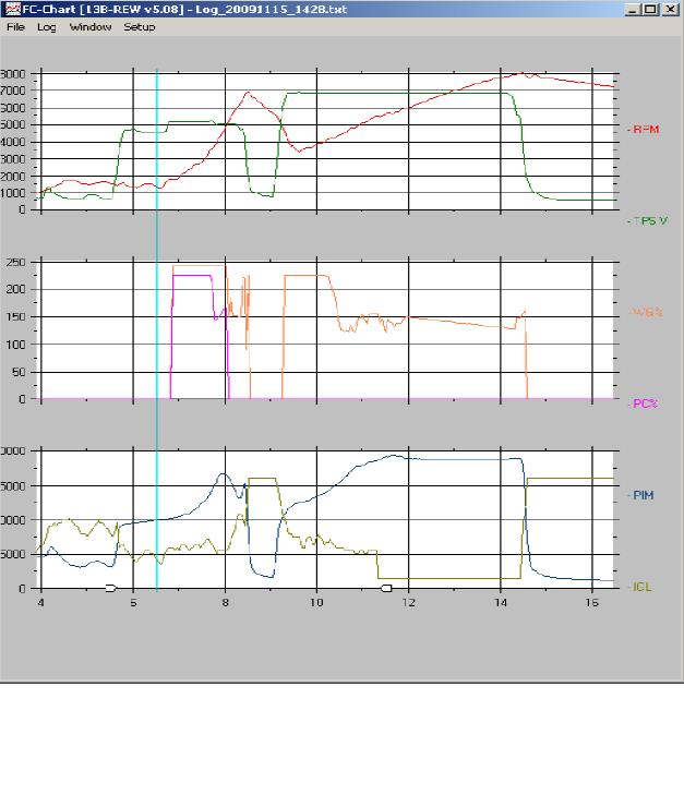
WG spring only
The first chart shows rpm and throttle; the second chart shows Pre Control and Waste Gate [solenoid] duties. Note that in this run the WG duty % signal does not drive the bleed solenoid, which is de-energized. The third chart shows boost (�PIM�, absolute pressure at the intake manifold, in PFC language) and ignition advance of the leading spark. PIM 10000 equals to approx. 0 psi (relative), PIM 15000 = a little less of 7.5 psi, and PIM 20000 = 14.75 psi
Before transition, boost stays just above the 7 psi WG spring pressure. After transition, boost increases linearly as the WG keeps opening. At 7000 rpm, the safety row is hit and the ignition advance drops to 4 degree. At t=6 sec, the throttle is reduced. Boost peaks at 1.21 Kg/cm2, then decreases. These results clearly disprove my hypothesis. Even with �zero� duty (solenoids de-energized), the boost creeps up to over 17 psi.
Moving on to compare the OE solenoid valve and the MAC�
Test pulls shown in the charts below are all in 2nd gear and at full throttle.
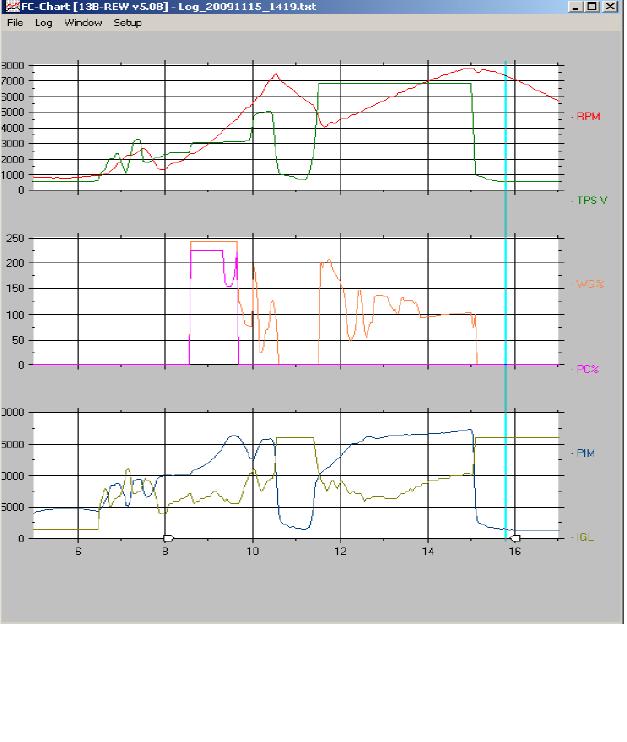
Secondary Duty = 30% - stock solenoid
At 14 sec, after the initial duty oscillations, boost has �stabilized� at 0.77 K/cm2, below the 0.90 target. At that point duty increase slowly, and so does boost. I guess this is the result of the closed-loop operation. When the throttle is released (at 7800 rpm) boost has reached 0.86 Kg/cm2.
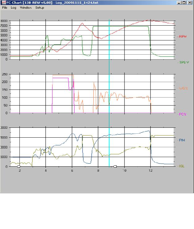
Secondary Duty = 30% - MAC solenoid
Boost builds up a bit quicker. After the initial duty oscillations, at 10 sec, boost is 0.80 Kg/cm2. As in the previous case, duty increases slowly. At 11+ sec boost is 0.85 Kg/cm2. However, now the boost starts creeping up as the WG is unable to divert enough energy. The PFC senses the rate change and attempts counteracting by starting reducing the solenoid duty. But there is no more time left. Throttle is released at 8100 rpm when boost has reached 0.97 Kg/cm2, overshooting the 0.90 Kg/cm2 because of the mechanical WG limitations.
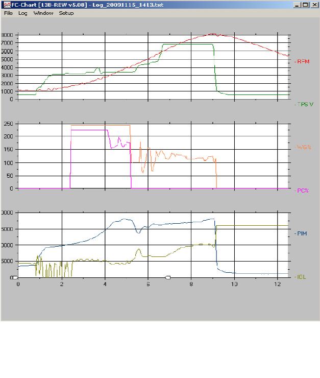
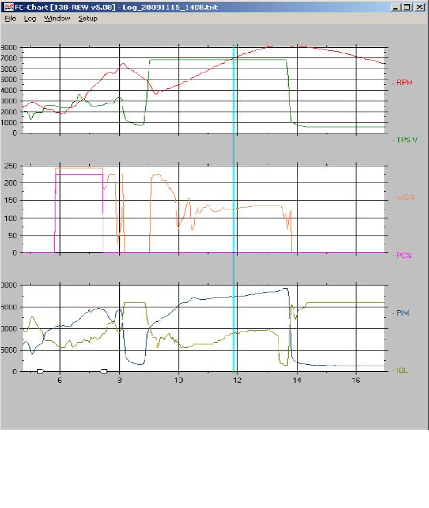
Secondary Duty = 40% - stock solenoid
At 8 sec boost is 0.81 Kg/cm2. Duty increases slowly. At 7800 boost creep takes off, PFC tries counteracting it. When throttle is released boost has reached 0.94 Kg/cm2
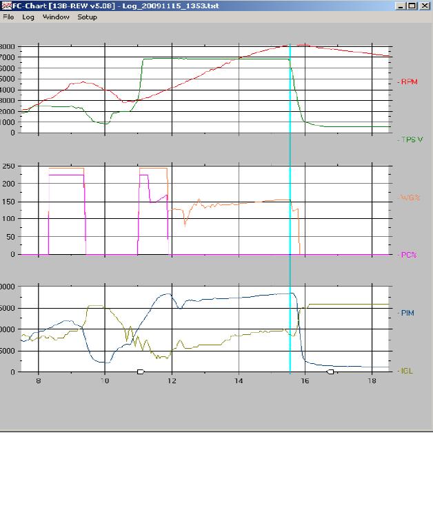
Secondary Duty = 40% - MAC solenoid
Boost 0.85 at before 12 sec. In this run, WG duty flattens at 52%, while boost keeps creeping up. At 13.5 sec duty drops dramatically. At about the same, time my safety row gets hit (1.00 Kg.cm2) and ignition advance gets pulled down to 5 deg. This combination effectively stops boost creep at 1.06 Kg/cm2 before throttle is lifted at 8360 rpm.
Fewer duty oscillations this time. Boost at 0.83 then rising as the duty increases slowly. 0.98 when throttle is released. Duty had flattened to 60% right before that.
Secondary Duty = 50% - MAC solenoid
Fewer duty oscillations here. Boost 0.87 at 10.3 sec. Duty increases slowly and flattens at 57%. Safety row hit at 12+ sec; duty drops a bit; boost creep is stooped at 1.07 Kg/cm2
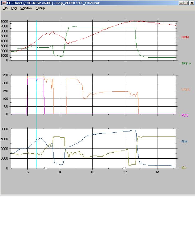
Secondary Duty = 60% - stock solenoid
Boost at 0.84 10 sec after the initial duty oscillation. Duty flattens at 69.5% with the boost at 0.99 Kg/cm2. Safety row gets hit immediately after. Duty decreases, yet boost peaks at 1.05 before throttle release.
-- END Part II ---
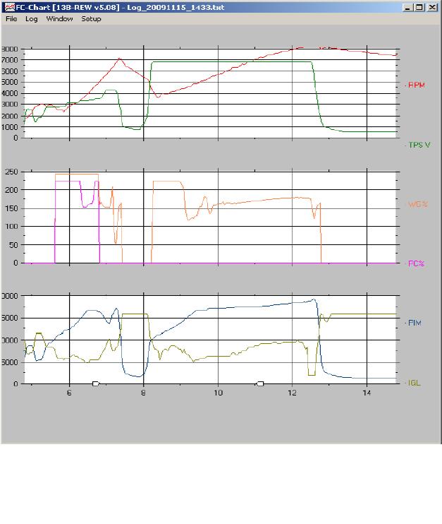
Secondary Duty = 60% - MAC
This, I find it very interesting. First, boost goes up really fast. Safety row is hit at 5500 rpm! Peak boost is 1.07 � same as the 50% duty case before. But then, duty decreases and keeps boost at 1.01. In the meantime, ignition advance is pulled to 4 deg.
I think these tests prove several things about PFC boost control.
1) It may not be adjustable as an AVC-R, but the PFC controls boost on sequential turbo cars just fine. Adjusting it does require some fiddling, but no more than the other stuff out there
2) logging solenoid duty is extremely useful in tuning an electronic boost controller. This cannot be done with external EBC's. Only standalones or factory ECU's (Subaru, Evo) can log solenoid duty.
3) The PFC is really two electronic boost controllers. It has two completely independent settings and solenoids for precontrol and wastegate, just like Mazda designed. This gives additional flexibility in tuning the boost pattern. A lot of people control boost with a single external EBC hooked into both actuators. This necessitates compromises.
Pre and post transition boost control are significantly different because the exhaust is flowing in different ways. When you hook a single EBC solenoid to both actuators, the precontrol door may be partly shut after transition. This causes extra restriction in the exhaust. From the factory the precontrol solenoid is always at 0% duty following transition and the PFC uses this same logic. 0% duty means the actuator is completely open. If you have one solenoid running at 50% duty to both actuators, the precontrol valve may only be open part way.
4) "feed" (as opposed to "bleed") style 3 port boost control, the kind you get from any external EBC solenoid (Greddy etc) is more responsive than the 2 port solenoid used from the factory. It is very common for Subaru owners to switch from an FD style 2 port setup to a 3 port solenoid, while reprogramming their stock ECU's boost controller.
5) as in any boost control system, the wastegate needs to be appropriately sized. Sandro isn't allowed to port his wastegate according to class rules, so he retards ignition timing if overboost does occur.
Bummer about the boost creep at high RPM, but interesting to see the effects of the different solenoid at the same duty settings.
If I'm not mistaken, you've re-routed the vacuum lines going into the wastegate and precontrol actuators. Where is the boost solenoid getting its pressure reference from? Is it possible that the additional plumbing you've installed could be causing a pressure drop (preventing the actuator from opening completely)? The OEM pressure lines between the compressor outlet and WG actuator are pretty short.
I could be wrong (my setup is much tamer than yours... not nearly as much flow), but you could get lucky and acheive your desired boost target without porting the wastegate flapper door. I'm fairly certain a local guy was running non-sequential twins at wastegate spring pressure without porting the wastegate (catless midpipe installed).
edit: I've got my standalone (not a PFC) wired and configured to allow for independent control of the prespool and wastegate solenoids (stock twins, stock actuators and solenoids). Holding the wastegate shut and regulating boost using the prespool duty cycle only yields a much quicker spoolup than using the wastegate at low RPM.
Holding the wastegate shut and regulating boost using the prespool duty cycle only yields a much quicker spoolup than using the wastegate at low RPM.
exactly. I don't see any advantages to an external boost controller (Greddy etc) on a car with sequential twins and a standalone (usually PFC). it's definitely worse than the stock design, no doubt about it. If the restricter pills and solenoids are the issue you can swap them out as Sandro has done. It's a lot cheaper than buying an external EBC.
You should try switching to a 3 port solenoid and see how it works on your setup. The solenoid Sandro is using is the same as the AEM and Haltech solenoids, he just bought it from the manufacturer directly instead of paying the huge markup.
If I'm not mistaken, you've re-routed the vacuum lines going into the wastegate and precontrol actuators. Where is the boost solenoid getting its pressure reference from? Is it possible that the additional plumbing you've installed could be causing a pressure drop (preventing the actuator from opening completely)? The OEM pressure lines between the compressor outlet and WG actuator are pretty short.
The PC actuator plumbing is untouched for the time being. Now that I am satisfied with the MAC valve, eventually will use two, one for the WG and one for the PC.
The reference pressure is the stock MAP sensor in the intake manifold, and this is what the PFC sees to send the pulse signals to the solenoids (OE bleed or MAC feed).
Yes, there is some extra tubes right now (and also the bleed line is not capped). But I believe the effect is non significant. Consider there is no air "flowing" continuously. Extra tube is more like having some more extra volume in the actuator. It will probably slow down the response a bit (takes a bit longer to pressurize a bigger volume) but that is not relevant for the purpose of the test, which was to judge the effectiveness of the 3-port valve v. the OE 2-way valve.
Originally Posted by scotty305
I could be wrong (my setup is much tamer than yours... not nearly as much flow), but you could get lucky and acheive your desired boost target without porting the wastegate flapper door. I'm fairly certain a local guy was running non-sequential twins at wastegate spring pressure without porting the wastegate (catless midpipe installed).
No, that is disproved by the first pull log with no WG control. The matter is, the degree of boost creep is highly dependent on how you apply throttle. I have other logs (which I have not posted) where I apply less throttle, and I am not getting any boost creep even at very high rpm.
No, that is disproved by the first pull log with no WG control. The matter is, the degree of boost creep is highly dependent on how you apply throttle. I have other logs (which I have not posted) where I apply less throttle, and I am not getting any boost creep even at very high rpm.
Yeah less throttle opening means less airflow even at same boost level. Sounds like you will have to add a restriction to the exhaust to keep flow down. Unfortunately that will also hurt power. Maybe you should just tune for the higher boost levels instead. Or is that not allowed either?
... Sounds like you will have to add a restriction to the exhaust to keep flow down...
No way!
Originally Posted by Dudemaaanownsanrx7
Maybe you should just tune for the higher boost levels instead. Or is that not allowed either?
Yes, it is allowed. But I am currently limited by the stock injectors. I will upgrade the injectors and run higher boost. Additionally, as you can see, retarding ignition timing also works well to keep boost in check.
Man who comes up with these rules, cant port the wastegate, even though it wouldn't do much to power. But you can crank the boost up which certainly will add power. Odd.
Man who comes up with these rules, cant port the wastegate, even though it wouldn't do much to power. But you can crank the boost up which certainly will add power. Odd.
You are right, it does not sound logical. But the "general" principle in the class is not to allow any mods to the engine/turbo "hardware" while freeing up air/fuel delivery, and power management control, including boost.
I wanted to share some experience trying the MAC solenoids out for the first time.
First, if you want to compare performance of the MAC vs the stock solenoid setup, there is a very simple way to do it that lets you swap back and forth by simply plugging in the right solenoid to the ECU harness and swapping one section of hose. The key to it working is to notice that for either test config, the solenoid not being used happens to default to a configuration (closed for the OE and port 2 to 3 passthru for the MAC) that enables the configuration under test. I've attached a diagram.
1) Test the OE solenoid when it is unplugged from the harness and verify it holds the pressure you want to boost. This is just a test that you don't have a defective solenoid.
2) Test the MAC solenoid when it is unplugged and verify that it passes air from port 2 to 3. This is just to make sure you understand what port is what.
3) Make a small piece of hose with the stock pill in it, or use the OE hose.
4) Run longer than usual sections of hose from port 2 of the MAC and the actuator, so that it is easy to get to the ends.
5) When you want test with the MAC, plug in the MAC to the ECU harness, and attach a section of hose to your long ends that doesn't have a pill.
6) When you want to test the OE solenoid, plug in the OE solenoid, and attach the section of hose to your long ends that does have a pill.
Don't worry about running longer hose than usual. I noticed zero difference between this configuration and the final MAC solenoid install I did with nice short hose lengths. Hose length doesn't seem to affect the tuning at all, as near as I can tell.
Second, understand that the boost level is controlled with the PowerFC duty cycle setting, not the threshold setting. I'm going to guess that the PowerFC utilizes a fuzzy logic controller (very popular in Japan, certainly around the time the PFC was developed) that does its own internal tuning trying to get flat boost with whatever duty cycle you give it. The duty cycle is the number it uses to start this tuning process with. The threshold number is just used to decide if this internal tuning process is running out of control or not. The PowerFC will panic and drop duty cycle to 10% if it sees boost climbing "too fast", and as a last-gasp effort, it will trigger a fuel cut if boost is 0.25 kg/cm^2 over the threshold. In my experience, what the PowerFC thinks is "too fast" seems to depend on how tight the threshold is. The tighter the threshold, the more the PowerFC has a tendency to panic. So moving the threshold up a bit if you see duty cycle drop-outs and the resulting oscillatory boost pattern gives the fuzzy controller more room to do its thing.
Anyway, in my testing on new sequential BNRs, using a MAC to control the PC actuator worked great right away. When I used the MAC to control the WG, I started very conservative with low numbers for duty cycle and threshold, and got a lot of duty cycle drop out and a resulting flat but oscillatory boost pattern. It took some time to figure out how to get rid of these dropouts (actually Steve Kan was the one that got rid of them, not me, by having enough experience in a tuning session to feel comfortable raising the threshold).
I didn't use any pills with the MACs. It is possible a pill might help with dropouts too, but I didn't test that.
The MACs do definitely provide better, lower latency control - absolutely dead flat boost patterns (except at the transition, of course).
Can you post a chart of your "flat but oscillatory boost pattern", possibly showing WG/PC duty cycle as well?
Sure, here are some example 2nd gear wide-open-throttle runs:
This is an example of wastegate dropout I mentioned below, from some very early (poor) tuning. I think this is with the stock pre-control and stock wastegate solenoids, right after I installed the BNRs and before I installed the MACs, but it was the best plot I could find that shows the problem. This behavior is what caused me to think I needed the MACs. I think the tuning settings were .7 41%, .7 65%.
WOT, stock PC and WG and stock pills, boost settings .7 41%, .7 65%
Here is another run with both the MACs and stock WG installed per the diagram in my previous post, with the stock WG solenoid plugged in (and thus controlling boost). Since the precontrol MAC worked great right away, I never bothered comparing it to the stock precontrol. This plot and all subsequent are using the MAC to control the precontrol actuator. Note the stock solenoid also drops out once here, even with the lowered settings. At this point with my tuning efforts, I was trying to just lower all the settings hoping to get rid of the drop outs and get to a stable boost control, and also investigate if there was some issue with the WG MAC by comparing it to the stock WG. It hadn't occurred to me yet that maybe I should RAISE the threshold and drop the duty cycle.
WOT Run, Boost Settings .6 45%, .6 40%, with stock wastegate and stock pill enabled.
And here is the corresponding run with the WG MAC plugged in and thus controlling boost, with the exact same settings. You can see the resulting control is actually quite similar, and also has a single WG dropout right after transition. If I had done a better job keeping my foot on the throttle, they would be an even better comparison! Anyway, this told me that the WG MAC was working at least as well as the stock solenoid, which at the time was good to know.
WOT with MAC WG solenoid enabled, settings .6 45%, .6 40%
Finally, just as a reference, here is the boost pattern I am using right now with the MACs, in their final install configuration, so with short hose lines and the stock solenoids completely removed. The (very) large boost drop at transition I think is caused by the very large intercooler I have (a Rotary Extreme Monster V-Mount). The intercooler has two intake pipes, one for the primary boost and one for the secondary, with a divider welded in to separate the intake bell between these pipes. As a result, the primary uses half the intercooler and the secondary the other half. This design is meant to reduce boost lag, but I think it may also increase the boost drop at transition - although I'm not really sure about any of that - just be aware that the large drop at transition is likely something to do with my car, not the MACs.
WOT run using MACs with short hoses, settings 1.05, 58%, 1.05 63%
Hope all that helps someone else try the MACs out with a little more confidence.
Sure, here are some example 2nd gear wide-open-throttle runs:
This is an example of wastegate dropout I mentioned below, from some very early (poor) tuning. I think this is with the stock pre-control and stock wastegate solenoids, right after I installed the BNRs and before I installed the MACs, but it was the best plot I could find that shows the problem. This behavior is what caused me to think I needed the MACs. I think the tuning settings were .7 41%, .7 65%.
WOT, stock PC and WG and stock pills, boost settings .7 41%, .7 65%
Thank you!
My logs have looked the same as your first chart with the WG cycling and fluctuating boost and you're the first person I've seen that fixed it without using MBCs
Do you attribute the fix (ie smooth boost level) to changing the duty cycles, changing the threshold or something else?
Thank you!
My logs have looked the same as your first chart with the WG cycling and fluctuating boost and you're the first person I've seen that fixed it without using MBCs
Do you attribute the fix (ie smooth boost level) to changing the duty cycles, changing the threshold or something else?
Well first, I'm not the person that ended up fixing it and don't pretend to have a lot of experience in this. That said, there are a few things I would try if I still had the problem:
- Raise the threshold and lower the duty cycle, based on the theory that if the threshold is too close to the duty cycle and the PFC sees a too rapid boost rise, it triggers safety software in the fuzzy logic controller, and that is what is causing it to drop out.
- For my car at least, another theory is that the drop-outs are caused by the large drop my system has during transition. It seems unlikely to me that a fuzzy logic controller for boost control coded up in 1993, would have anticipated that large a transition droop without freaking out. If this theory is right, perhaps raising boost above your target during primary, so as to reduce the transition droop might help.
- One could add a pill to the line to see if simply low-pass filtering the pressure changes in the actuator helps smooth things out. Note the MAC provides the option to put a pill on the pressure side (active only during actuator pressurization, like the stock system), on the vent side (so only active during vent) or on the line between the MAC and actuator, which would make it active during both pressurization and vent. I haven't tried any of this. You would also need to play with different diameter pills. If the problem was too rapid boost rise, it might be useful to try a pill only on the vent side, since this would hold pressure in the actuator longer, reducing boost. I think I have all that right - please double-check my logic before proceeding...
Whatever your experience, success or failure, post it here.
 11-17-09, 03:58 PM