Need help finishing off this wiring harness diagram...
 07-24-09, 03:48 AM
#1
Rotary Enthusiast
Thread Starter

Join Date: Nov 2002
Location: Oahu, Hawaii
Posts: 792
Likes: 0
Received 0 Likes
on
0 Posts
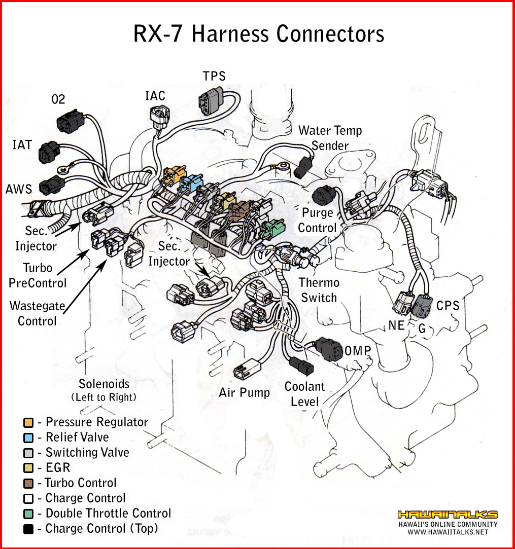
I'd appreciate some help in getting this right...it's a WIP for my reference photos project.
[ https://www.rx7club.com/3rd-generation-specific-1993-2002-16/rx-7-fd3s-reference-photos-project-802817/ ]
Thanks a bunch!
[ https://www.rx7club.com/3rd-generation-specific-1993-2002-16/rx-7-fd3s-reference-photos-project-802817/ ]
Thanks a bunch!
 07-25-09, 11:31 AM
#2
Recovering Miataholic
ArchangelX,
According to my 1994 Workshop Manual, page Z-32, what you have designated the "thermo switch" is actually the engine coolant temperature sensor (connector B-41), and what you have designated the "Water Temp Sender" is the sensor for the temperature gauge called by Mazda the "Water Temperature Sensor (Meter)," connector C1-04.
I take it you have reproduced the basic picture from the Assembly section C of the workshop manual.
I believe you have mis-identified the connectors labeled "Turbo Precontrol" and "Wastegate Control." You show three connectors to the left and slightly below the text "Thermo Switch." The two smaller, same-size connectors are the two that connect to the "Duty Solenoid" bolted to the lower front side of the UIM. You can see the plugged-in interface in section C, "Surge Tank Assembly," step 6 figure, "Connect the duty solenoid valve as shown in the figure." They install as they are drawn, no cross-over. The one on the side away from the engine is identified as "Turbo Precontrol" and the one nearest the engine as "Wastegate Control" in the "Vacuum Hose Routing Diagram" in section F of the manual. (See "I" and "J".) The top connector of the three, I believe, is the "Charge Relief" solenoid valve connector ("H" of the same diagram).
The two connectors you have labeled "Turbo Precontrol" and "Wastegate Control" are (I believe) the "(Gray) Injector (Primary Rear)" and the "(Gray) Injector (Primary Front)" going left to right. The third one is (I think) the "(Gray) Injector (Secondary Front)." I also believe the connector you have labeled "Sec Injector" to the right of those three is actually the "Fuel Thermosensor" connector.
There are two unidentified connectors in the same cable as your "Sec. Injector" connector; I believe the lower, long straight one connects to the EGR Valve connector and is the "EGR Function Sensor" connector. The other making the right turn should be the "Turbo Control" solenoid valve connector that plugs into the valve bolted to the front side of the ACV valve body.
If I can find some pics to back this up from my year-ago work on the engine, I will post them.
Edit:
Pic 1 shows the Duty Solenoid with its two connectors; looking behind them and under the UIM you can just see the back of the "Turbo Control" connector on the front of the ACV body. Somewhat to the right of the Duty Solenoids you can see the Charge Relief Valve connector plugged in at the top of the solenoid rack.
In Pic 2 you can see the blue EGR connector behind hoses in front of the LIM front runner.
Pic 3 is view from left side with UIM off; you can glimpse a few connectors, but good look telling where they break out of their harnesses!
Pic 4 looking down at duty solenoid connectors, charge relief connector, etc.
Last edited by wstrohm; 07-25-09 at 11:40 AM. Reason: Adding Pics
07-25-09, 02:12 PM
#3
Rotary Enthusiast
Thread Starter
Join Date: Nov 2002
Location: Oahu, Hawaii
Posts: 792
Likes: 0
Received 0 Likes
on
0 Posts
Wow...lol...this is the second time I've asked for help in finishing this off. There must be alot of wrong people out there...lol...
I used the 1995 Mazda RX-7 manual to create it, as well as help from some people that work on RX-7s at Mazda, plus using feedback from here. I'll see if I can find the old thread.
I used the 1995 Mazda RX-7 manual to create it, as well as help from some people that work on RX-7s at Mazda, plus using feedback from here. I'll see if I can find the old thread.
07-25-09, 02:28 PM
#4
Rotary Enthusiast
Thread Starter
Join Date: Nov 2002
Location: Oahu, Hawaii
Posts: 792
Likes: 0
Received 0 Likes
on
0 Posts
07-26-09, 01:59 PM
#6
Recovering Miataholic
ArchangelX,
If those two connectors pointing down next to the solenoid rack are really the primary injector connectors, then my post #2 above is obviously wrong. Just ignore it.
If those two connectors pointing down next to the solenoid rack are really the primary injector connectors, then my post #2 above is obviously wrong. Just ignore it.
07-26-09, 08:58 PM
#7
canadian monster
iTrader: (2)
Join Date: Mar 2001
Location: Trois-Rivi�res, Qc, Can
Posts: 2,083
Likes: 0
Received 0 Likes
on
0 Posts
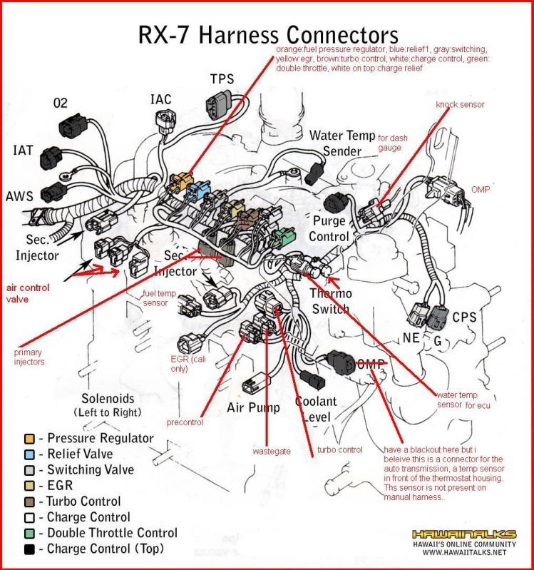
here, unsure between the fuel temp sensor and the turbo control since they both point in the same direction and physically they are all tied together but the fuel temp is green and the turbo control is black so...
Trending Topics
 07-29-09, 05:12 PM
#9
canadian monster
iTrader: (2)
Join Date: Mar 2001
Location: Trois-Rivi�res, Qc, Can
Posts: 2,083
Likes: 0
Received 0 Likes
on
0 Posts
hmm i beleive the thermo switch and the water temp sensor are one next to each other on the pic, just like on the car. Look closely at the pic, you can see there are two sensors close to each other. The thermo switch is the black round connector while the other one is green and more square, like any other temp sensor on the car (fuel or air)
 11-30-11, 10:14 PM
#13
Rotary Enthusiast
Thread Starter
Join Date: Nov 2002
Location: Oahu, Hawaii
Posts: 792
Likes: 0
Received 0 Likes
on
0 Posts
Unfortunately, no...I asked around but sorta ran outta help on confirming what's what. It still gives you a pretty good idea of where everything goes for the most part. 
12-11-11, 07:16 AM
#22
Brap Brap Brap
iTrader: (3)
Join Date: Jan 2010
Location: Pennsylvania
Posts: 981
Likes: 0
Received 0 Likes
on
0 Posts
Can anyone point me in the direction of where to find a wiring harness and/or vacuum hose routing diagram for a 1990 non turbo? I have the Haynes manual and FSM and followed them both almost exactly other then the few small changes Ive made but I am lost on the last 5 or 6 electrical connectors and 2 or 3 vacuum hoses. I cant find a wiring harness diagram other then this one and the Haynes manual kind of sucks for following the vac hoses not to mention they dont show the intake vac lines up against the fire wall.
12-14-11, 02:48 PM
#23
Rotary Enthusiast
Thread Starter
Join Date: Nov 2002
Location: Oahu, Hawaii
Posts: 792
Likes: 0
Received 0 Likes
on
0 Posts
12-14-11, 02:56 PM
#24

AWS and O2 connectors are switched, the AWS has a small offset on the connector and the inside cover for the terminals is orange. All others are lime green.
There is also a small connector missing which plugs into what I think is the emission harness. It's identical to the "water temp sender."
There is also a small connector missing which plugs into what I think is the emission harness. It's identical to the "water temp sender."