MSD 6AL and 2 step install Instructions
 06-29-10, 09:23 PM
#1
Full Member
Thread Starter

Join Date: Mar 2010
Location: Milwaukee
Posts: 123
Likes: 0
Received 0 Likes
on
0 Posts
MSD 6AL and 2 step install Instructions
Hey everyone, while searching for a MSD and 2 step wiring diagram I found a few threads that were very useful. However, most of these threads have more relays and wiring than I thought necessary for this setup. I was able to set up the 6AL box on the leading coils with a 2 step with 1 relay to cut the 2 trailing coils out so I figured I would share this info.
First off, I am not good with drawing wiring diagrams on a computer, but I will do my best to explain everything.
Alright, first thing I did was mount the MSD and 2 step in the drivers side rear bin. Obviously this requires extending wires to the engine bay so I bought 10 ft. of trailer wire that has 6 14 gauge wires loomed together. I also bought 1 single pole double throw 5 pin relay. I ran the wire up through the firewall and began splicing and cutting.
Now as far as wiring goes I followed the illustrated picture for the leading coil in this thread. https://www.rx7club.com/showthread.p...ht=msd+install
So that takes care of 4 of the 6 wires.
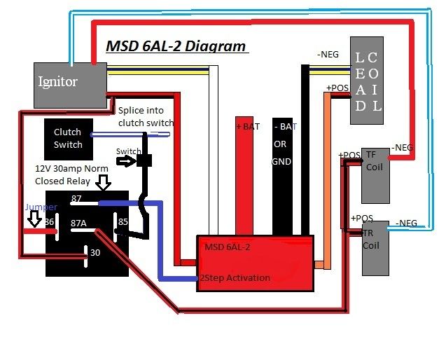
The next wire I cut was the power wire to the trailing coils and sent that back to pin 87a on the relay (this is the wire from the coil not the igniter)
The 12v source from the igniter goes to pin 30 on the relay and also has a jumper wire from pin 30 to pin 86 to give the relay its power
The next wire from the loom goes from pin 85 to the blue and white wire on the bottom clutch switch (this switche grounds to the relay when the clutch is depressed)
The final wire for the relay goes from pin 87 to the red wire on the 2 step.
So basically when you are driving normally with the clutch out there is power to everything minus the 2 step. When you press the clutch in, the relay takes power from the trailing coils and gives it to your 2 step. So your 2 step activates and your power is cut on the trailing coils all with 1 relay.
If this has been wired like this before and already written up I apologize but I just couldn't find it.
First off, I am not good with drawing wiring diagrams on a computer, but I will do my best to explain everything.
Alright, first thing I did was mount the MSD and 2 step in the drivers side rear bin. Obviously this requires extending wires to the engine bay so I bought 10 ft. of trailer wire that has 6 14 gauge wires loomed together. I also bought 1 single pole double throw 5 pin relay. I ran the wire up through the firewall and began splicing and cutting.
Now as far as wiring goes I followed the illustrated picture for the leading coil in this thread. https://www.rx7club.com/showthread.p...ht=msd+install
So that takes care of 4 of the 6 wires.
The next wire I cut was the power wire to the trailing coils and sent that back to pin 87a on the relay (this is the wire from the coil not the igniter)
The 12v source from the igniter goes to pin 30 on the relay and also has a jumper wire from pin 30 to pin 86 to give the relay its power
The next wire from the loom goes from pin 85 to the blue and white wire on the bottom clutch switch (this switche grounds to the relay when the clutch is depressed)
The final wire for the relay goes from pin 87 to the red wire on the 2 step.
So basically when you are driving normally with the clutch out there is power to everything minus the 2 step. When you press the clutch in, the relay takes power from the trailing coils and gives it to your 2 step. So your 2 step activates and your power is cut on the trailing coils all with 1 relay.
If this has been wired like this before and already written up I apologize but I just couldn't find it.
 12-02-10, 10:32 PM
#2
I just wired up my new Crane ignition HI-6DSR with the built in 2 step, and I used the instructions above for wiring the relay and it works great. Thank you. I also wanted to add, you can get the correct relay at advance auto parts, but you have to ask for a BWD relay part number R3177. This is a 5 pin normally closed relay, when you look at the diagram on the correct relay needed you will see it shows 87a connected to 30, then when it switches it connects 87 to 30.
The universal 5 pin relay they sell in the isle will not work, it has two 87 pins and not a 87a pin, and it's normally open, meaning the two 87's will get connected to 30 when the switch is activated with power and ground from 85 and 86, and none are connected until the switch is activated.
I removed the IC pipe to the elbow, UIM, oil fill tube, then the little wire harness that has the coil connectors and cut the red/black wire a couple inches away from the main harness connector where it is still just one wire before it splits off to supply power to the coils at the top terminal of the trailing coil plugs. the trailing coil + wire from the ignitor/harness side goes to 30 and 86.
The other end of the wire that you cut that goes to the + side of the trailing coils (top terminal in the coil plugs) connects to 87a. The yellow wire 2 step activation wire from the crane ignition goes to 87. The blue/white stripe wire from the clutch switch goes to 85.
I wired mine up with clutch switch, there really is no reason to wire it up to the horn switch unless you really want to have an extra button to worry about when you are launching at the drag strip. With the clutch pedal pushed it just a little bit, just past where the clutch switch is fully extended, the trailing coils turn off and 2 step is activated and ready to go when you rev and hit the desired rpm set for the 2 step. This crane is really nice, it has two rotary dials for the 2 step and two for the maximum rev limiter, so each rev limiter is adjustable in 100 rpms increments.
Either it's just me and I didn't realize it before with my Jacobs FC1000, but man this thing revs extremely smooth and quick. Idles good too.
Another thing you can do to disable the 2 step relay, so the trailing coils always stay on like normal and the clutch does not activate the 2 step, just simply put a switch on your wire that goes from the clutch switch wire to pin 85 on the relay. This way the relay won't work, and nothing different will happen when using the clutch, trailing coils will stay on and 2 step won't activate. Otherwise your engine will always have a lower rev limiter when you rev the engine with the clutch in, to what ever you have the 2 step stage rev limiter set to. I figured this was no problem so I did not choose to add the extra switch.
12-04-10, 01:18 PM
#4
Actually the switch is a good idea cause my car wouldn't start with the clutch in (trailing coils off), I usually like to start it with the clutch in, so I'll wire up a little switch for under the dash probably.
It does start when it is warm with clutch in, but didn't want to start when it was cold with the clutch in.
It does start when it is warm with clutch in, but didn't want to start when it was cold with the clutch in.
12-05-10, 10:41 AM
#5
Full Member
Thread Starter
Join Date: Mar 2010
Location: Milwaukee
Posts: 123
Likes: 0
Received 0 Likes
on
0 Posts
Very good point. I never thought of that either, but never had problems starting with the clutch in. Also just to give a heads up for other people looking for a 2 step, msd now has a 6al2 box that has the 2 step built in, much more compact and less pieces, but still the same wiring.
10-25-12, 08:54 AM
#6
Ok bringing this back from the dead. Ive looked over a few other peoples write ups on installing an ignition amp with a 2 step and so far this seems the simpliest way of doing it. I plan to use the msd 6al-2 setup for the leading coils and use this method of a relay to cut the power from the trailing while in 2step. I was bored and felt like contributing to the community and modified someone elses diagram. Please let me know if this is correct.

09-04-13, 12:52 AM
#7
Ok bringing this back from the dead. Ive looked over a few other peoples write ups on installing an ignition amp with a 2 step and so far this seems the simpliest way of doing it. I plan to use the msd 6al-2 setup for the leading coils and use this method of a relay to cut the power from the trailing while in 2step. I was bored and felt like contributing to the community and modified someone elses diagram. Please let me know if this is correct.
Trending Topics

Thread
Thread Starter
Forum
Replies
Last Post
trickster
2nd Generation Specific (1986-1992)
25
07-01-23 04:40 PM

