just got done figuring out how to fix an FD odometer
 04-14-08, 09:51 AM
#51

But, there doesn't appear to be any obvious physical damage.
The black stuff you referred to just appears to be flux, like the stuff around the solder joints of the capacitors you installed.
(bypassing the obvious joke here)
 12-19-08, 03:46 PM
#53

Thanks Matt for the "Fix". I just completed repairing my speedo board with the blank odometer gremlin.
If there are no obvious signs of leaking or damage (bulging, corrosion, etc.) with the two capacitors; replace both the 1000 uF 6.3v 105C and the 10uF 50v 105C. I would not change out all at the same time as you just up your chances for screwing something up and you will not know which cap. fixed the problem. You can hook the dash back up and test it without snapping it back in place. If it does not work, it only takes 15 to remove and disassemble the unit again. Remember to put the cap's on the board with the white stripe facing the minus sign (-) in a circle. Otherwise the odo will remain blank. Don't ask...
Also, the blank odo will affect your cruise control input. The CC will hunt/surge for a speed and then kick off. The signal from the speed sensor switch (on the tranny) goes through the speedo/odo and then to the CC. Once you replace the two cap.'s, the CC will function as normal.
Mouser Electronics (www.mouser.com) carries all of the Nichicon cap's and there is no order limit. I ordered all the cap's on the board in "threes" plus some extra stuff and with shipping it came to less than $20. The cap's are pennies each...literally. The Mouser P/N for the 10uF is 647-UVZ1H100MDD and the 1000uF is 647-UVZ0J102MPD. If you drop the "647" that will be the Nichicon stock number.
If you want to make this job a breeze. Forget the solder wick and get a "desoldering iron", $11 at Radio Shack. You'll never use wick again. Makes for a quick clean removal of components. If you have a desoldering iron and soldering iron plugged in at the same time; you can have the speedo board apart and back together again in 15 minutes or less and you won't be able to tell you've been in there. Solder tool kit (heat sink, and some probe/brush implements) ($6) and some tinning/tip cleaning compound ($6) from Radio Shack made things spiffier too. I used .022" rosin solder as anything larger MAY put down too much solder.
I am not an electronics guy at all...and not overly mechanical. I practiced on an old computer board, removing all components and then soldering them on again. Maybe an hour of practice...it is well worth it before tearing into the real thing if don't have your soldering chops down cold. I probably soldered something twice in my life before this. Don't let it scare you.
I also fixed the air bag Diagnostic Module which I will post a separated thread on later with pictures.
12-20-08, 05:15 PM
#54
WOW, I have never soldered anything ever before and I went ahead and followed these step by step instructions and saved myself hundreds of dollars.I took a chance taking apart the guage cluster but once i got to board the exact two capacitors that turbo blue had burned out were the same ones I had burned out on mines. Went ahead and soldered capacitors in place and VOILA..good as new.
The following users liked this post:
rousu (11-17-18)
01-03-09, 03:50 PM
#57

Forgive me if I missed this info - I looked through quite a few threads and did not see this, but what were the symptoms of you guys' ododmeters that were fixed using these instructions? Mine is intermitent and sometimes (most of the time)the check engine light comes on once when it fails. I was instructed by my car's previous owner that it was the speedo sensor (thanks dgeesaman) but replaced that this morning and I have the exact same issue as before. I'm thinking I should have done more homework before believing that was the problem...
Thanks for any help guys.
Thanks for any help guys.
The following users liked this post:
rousu (08-23-20)
01-04-09, 01:01 PM
#58
Basically...one morning you switch on the ignition and the odo is blank. The back light will be on; but no digits...faint gray digits visible...but they are just the indicators not the actual mileage. If it is intermittent...you are probably looking at the same problem. I do not think it would have anything to do with your "check engine" light as the signal only comes from the speedo sensor.
Cruise control will probably be "hunting" also as the signal from the odo goes to the CC also.
Nine times out of 10 it is just the 6.3v 1000uF capacitor that is going bad on the speedo board. The 50V 10uf is the next trouble maker. Since the life of an electrolytic capacitor is roughtly 15 years...I'd replace all of them and you might not have to worry for a long time. Having said that, I had to replace the 6.3v capacitor again as it failed one week after I rebuilt the speedo board...so new components can go **** up too. Luck of the draw I guess...
By-the-by, if you download the service manual (body electrical) there are troubleshooting steps for the cruise control that will tell you if the speedo sensor is bad along with the other components of the system...saves you some aggravation.
The following users liked this post:
LegoMontego (03-19-21)
01-04-09, 04:09 PM
#59
Full Member
Join Date: Dec 2006
Location: Oahu
Posts: 221
Likes: 0
Received 0 Likes
on
0 Posts
It's a company code of ethics to build products that cover not just current needs, but future needs as well. Too bad American companies don't have the same attitude as Panasonic. I got to change my odometer capacitors too, just a little to lazy to rip out the console cluster. Thanks for the heads up Dave, most of your posts are short and to the point.
01-04-09, 05:10 PM
#60
I think you'll find that...like most everything else...the cap.'s are made in China by a handful of companies and labeled for the end user/supplier. Just like batteries, bearings and the like. Nichi and Panasonic components are probably made at the same facility(ies).
01-06-09, 12:59 PM
#61
I probably should start this as a separate thread, but since it is still in the realm of troubleshooting the blank odometer problem I'll just tack it on here.
Since replacing the 6.3v 1000uF and 50v 10uF cap's originally, I have had 2 episodes of the odo going blank again. As mentioned a few posts up from this one, I thought my 1st post-repair failure was due to a bad "new" capacitor. I replaced the two cap's with new again...and all was well...until today.
After driving the car for several days with no trouble, I attempted to start the car and all I got was starter chatter. All warning lights worked (including odo), engine just would not turn over. Since I had been working on the car with the battery ground cable removed a few days ago...I decided to re-check the connection and found it ever so slightly loose. I could wiggled it back a forth just a hair. So I removed it and tightened it again...got back in the car...turned the ignition on...engine starts...and NO FRIGGIN' ODO
This triggered a memory from the 1st failure after repair. I had been working on the air bag Diagnostic Module after the 1st repair. I had disconnected the negative battery cable while R&R'ing the module. When I hooked the neg. cable back up to test my Diagnostic Module repair...I had NO ODO. I chalked this up to a bad "new" capacitor. Now, again after fiddling with the negative battery cable NO ODO. Hmmm, me thinks this is not coincidence.
So I chat with my old man who is a retired electrical engineer from the Rocket Factory (NASA)...he babbles some mumbo jumbo which is way above my head and basically says, "disconnect the positive battery cable, wait one minute and connect it, then check your odo. display again.". WTF...it is working now.
Anybody got a good reason why disconnecting the neg. cable knocks the odometer off line? Why removing the pos. cable brings it back? My old man is holding out on me.
01-06-09, 02:55 PM
#62
Full Member
Join Date: Dec 2006
Location: Oahu
Posts: 221
Likes: 0
Received 0 Likes
on
0 Posts
I probably should start this as a separate thread, but since it is still in the realm of troubleshooting the blank odometer problem I'll just tack it on here.
Since replacing the 6.3v 1000uF and 50v 10uF cap's originally, I have had 2 episodes of the odo going blank again. As mentioned a few posts up from this one, I thought my 1st post-repair failure was due to a bad "new" capacitor. I replaced the two cap's with new again...and all was well...until today.
After driving the car for several days with no trouble, I attempted to start the car and all I got was starter chatter. All warning lights worked (including odo), engine just would not turn over. Since I had been working on the car with the battery ground cable removed a few days ago...I decided to re-check the connection and found it ever so slightly loose. I could wiggled it back a forth just a hair. So I removed it and tightened it again...got back in the car...turned the ignition on...engine starts...and NO FRIGGIN' ODO
This triggered a memory from the 1st failure after repair. I had been working on the air bag Diagnostic Module after the 1st repair. I had disconnected the negative battery cable while R&R'ing the module. When I hooked the neg. cable back up to test my Diagnostic Module repair...I had NO ODO. I chalked this up to a bad "new" capacitor. Now, again after fiddling with the negative battery cable NO ODO. Hmmm, me thinks this is not coincidence.
So I chat with my old man who is a retired electrical engineer from the Rocket Factory (NASA)...he babbles some mumbo jumbo which is way above my head and basically says, "disconnect the positive battery cable, wait one minute and connect it, then check your odo. display again.". WTF...it is working now.
Anybody got a good reason why disconnecting the neg. cable knocks the odometer off line? Why removing the pos. cable brings it back? My old man is holding out on me.
Since replacing the 6.3v 1000uF and 50v 10uF cap's originally, I have had 2 episodes of the odo going blank again. As mentioned a few posts up from this one, I thought my 1st post-repair failure was due to a bad "new" capacitor. I replaced the two cap's with new again...and all was well...until today.
After driving the car for several days with no trouble, I attempted to start the car and all I got was starter chatter. All warning lights worked (including odo), engine just would not turn over. Since I had been working on the car with the battery ground cable removed a few days ago...I decided to re-check the connection and found it ever so slightly loose. I could wiggled it back a forth just a hair. So I removed it and tightened it again...got back in the car...turned the ignition on...engine starts...and NO FRIGGIN' ODO
This triggered a memory from the 1st failure after repair. I had been working on the air bag Diagnostic Module after the 1st repair. I had disconnected the negative battery cable while R&R'ing the module. When I hooked the neg. cable back up to test my Diagnostic Module repair...I had NO ODO. I chalked this up to a bad "new" capacitor. Now, again after fiddling with the negative battery cable NO ODO. Hmmm, me thinks this is not coincidence.
So I chat with my old man who is a retired electrical engineer from the Rocket Factory (NASA)...he babbles some mumbo jumbo which is way above my head and basically says, "disconnect the positive battery cable, wait one minute and connect it, then check your odo. display again.". WTF...it is working now.
Anybody got a good reason why disconnecting the neg. cable knocks the odometer off line? Why removing the pos. cable brings it back? My old man is holding out on me.
This charge and discharge cycle is used for various methods in controlling electrical outputs, depending on how the circuit is designed. I haven't looked at the schematic of the odometer, so can't tell what exact function these capacitors are playing. But basically there is some mechanical input to determine revolutions and converting it to digital output readings for mileage.
01-06-09, 03:52 PM
#63
Hey...if you find a schematic for the odo/speedometer board...give me a shout. It is absent from any service manual I have.
I have a very basic concept of how capacitors and other electronic components work...very basic...so I understand the what-N-how the little buggers function. What I do not understand is why every other time I've disconnected the negative battery cable in the last 15 years I have not had the odometer go "blank"? This has occurred only after I have repaired it. And why would pulling the positive battery cable bring it back to life? There is no battery back up that I can see...so that is out (unless I'm wrong).
I'd be curious if anyone else who has replaced the 2 cap's on their speedo board has had a similar experience? Anyone want to pull their battery neg. cable and see if the odo disappears? No guts...no glory!
05-02-09, 08:34 PM
#64
Can anyone tell me where the 25v 47uf cap goes? I accidentally put in a 50v 1uf, but I'm not sure which one I got wrong.
I ordered a double set of all of the capacitors listed above thinking that it was a complete list. I also ended up removing C16, a 50v 2.2uf that I don't have a replacement for. My fault for not paying attention.
I ordered a double set of all of the capacitors listed above thinking that it was a complete list. I also ended up removing C16, a 50v 2.2uf that I don't have a replacement for. My fault for not paying attention.
05-11-09, 06:18 PM
#65
Can anyone tell me where the 25v 47uf cap goes? I accidentally put in a 50v 1uf, but I'm not sure which one I got wrong.
I ordered a double set of all of the capacitors listed above thinking that it was a complete list. I also ended up removing C16, a 50v 2.2uf that I don't have a replacement for. My fault for not paying attention.
I ordered a double set of all of the capacitors listed above thinking that it was a complete list. I also ended up removing C16, a 50v 2.2uf that I don't have a replacement for. My fault for not paying attention.
 05-12-09, 11:20 AM
#66
C1 50v 10uf
C2 25v 47uf
C3 6.3v 1,000 uf
C4 50v 1uf
C5 ?
C6 50v 1uf
C7 ?
C8 ?
C9 50v ?uf
C10 ?
C11 50v 2.2uf
C12 50v 10uf
C13 50v 1uf
C14 ?
C15 ?
C16 50v 2.2uf
C17 50v 1uf
05-19-09, 03:37 PM
#67
Hey...if you find a schematic for the odo/speedometer board...give me a shout. It is absent from any service manual I have.
I have a very basic concept of how capacitors and other electronic components work...very basic...so I understand the what-N-how the little buggers function. What I do not understand is why every other time I've disconnected the negative battery cable in the last 15 years I have not had the odometer go "blank"? This has occurred only after I have repaired it. And why would pulling the positive battery cable bring it back to life? There is no battery back up that I can see...so that is out (unless I'm wrong).
I'd be curious if anyone else who has replaced the 2 cap's on their speedo board has had a similar experience? Anyone want to pull their battery neg. cable and see if the odo disappears? No guts...no glory!
I have a very basic concept of how capacitors and other electronic components work...very basic...so I understand the what-N-how the little buggers function. What I do not understand is why every other time I've disconnected the negative battery cable in the last 15 years I have not had the odometer go "blank"? This has occurred only after I have repaired it. And why would pulling the positive battery cable bring it back to life? There is no battery back up that I can see...so that is out (unless I'm wrong).
I'd be curious if anyone else who has replaced the 2 cap's on their speedo board has had a similar experience? Anyone want to pull their battery neg. cable and see if the odo disappears? No guts...no glory!
WOW. Now that I realize it, my odometer went out RIGHT after relocating my battery. I moved it successfully to the rear storage bin. When I returned from out of town, the odometer was out!
I figured it was the capacitors that blew. Pulled the thing apart and found that they looked perfectly normal. I replaced them anyhow.
Put the whole thing back together and bingo, meter came back to life. It worked for a few days and then I put my battery charger on my batter while it was in the car. When I removed the trickle charger, the meter was out.
Now when I drive for 45-hour on interstate, meter will randomly cut on. After I shut the car off it will not reappear.
I'm going to pull my positive off and try the one minute wait.
05-31-09, 03:49 PM
#68
These things are definately finicky. Since I posted that it was working, it's gone out, come back, and is out again. I've replaced all but two capacitors. I've tried the battery disconnect-reconnect dance to no avail. Not sure what's going on.
BTW - all of the caps can be replaced without removing the speedo motor - needle nose pliers help.
BTW - all of the caps can be replaced without removing the speedo motor - needle nose pliers help.
05-31-09, 05:00 PM
#69
i replaced 2 capacitors on my board and everything seems to be working perfectly.. I did break the tripometer button though  ...that was a big pain in the ***, finally fixed it tho
BE CAREFUL OF THE TRIPOMETER BUTTON WHILE WORKING ON THE CLUSTER!!! take out the small long plastic black button while working on it!
...that was a big pain in the ***, finally fixed it thoBE CAREFUL OF THE TRIPOMETER BUTTON WHILE WORKING ON THE CLUSTER!!! take out the small long plastic black button while working on it!
10-20-09, 02:04 PM
#72
Recovering Miataholic
Apparently there were bad lots of these caps used by Mazda and others in the early '90s. The Miata's airbag system Diagnostic Module is known for the electrolyte leakage problem, and also although rarely, its ECU has the same problem. I haven't seen the pics in this thread either (late to the party), but here is what they can do to a printed circuit card when they leak (Miata Diagnostic Module).
12-04-09, 06:54 PM
#74

anyone have the original pics? Mine just went out today. Dunno if its cause of the cold weather or not. This car just won't stay in one piece for very long.
Also, does disconnecting the battery work too, that is if the capacitors aren't the problem?
Also, does disconnecting the battery work too, that is if the capacitors aren't the problem?
01-05-10, 05:16 AM
#75
Sequentially broken
Here are the instructions again with a different image host as the OP's is inactive.
Ok, it's 11:30 pm and I'm bored so I'll do the full tutorial and get it over with.
To start out, remove the cluster and gauge hood from the dash. Then remove the cluster from the back of the hood by removing 4 screws. The next thing that is needed is the proper tools. You will need a soldering iron (lower wattage preferred), some good electronic solder, some desoldering braid, and a phillips head screw driver.
After you have acquired the proper tools start by removing the clear plastic cover from the instrument cluster. This is done by removing two screws (in red) and popping the black clips down on the top and bottom of the cluster.

This is the view after removing the cover from the cluster

Now you are going to want to remove both the tachometer, the speedometer/odometer unit, and the connection that goes from the back of the cluster to the speedometer unit. The first thing is to remove the three screws that hold on the tachometer (in red). After you remove the tachometer, you will want to remove the one screw holding a cover over the electrical connection that goes to the speedometer (in green). Now turn the cluster over and remove the screw holding the trip reset button to the cluster. After you have disconnected the lead to the speedo and removed the trip reset button, you will want to remove the five screws holding the speedo to the cluster (in yellow).

After all of this is removed, now you get the speedo out of the cluster.

When you get the speedo out, you are going to remove the unit that includes the face and needle motor. This unit is easily removed (with basic soldering skills) heating the solder joints (in red) and using the desoldering braid to soak up the used solder. The best method to remove solder is to first heat the solder joint, and then place the desoldering braid over the solder joint and then placing the soldering iron tip over the joint, which is under the braid. It will require moving the braid around the connection until there is no solder left on this connection. Now be patient, if this is done correctly, after you remove the two (I think) screws located between these four connections, the motor and face will just fall off.

Once the motor and face are removed, here is the birds eye view.

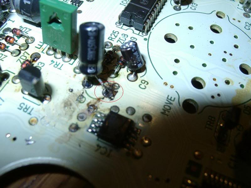
Now you can look around real good and see what is loose/burned/leaking. I had two capacitors that had leaked (explained in my previous post) and in the following picture I have already replaced the capacitors. One of the caps I replaced is substantially larger than the original one (I was too anxious to wait for one to be ordered). Below I have pictured what the burn (leak) will look like. I had already soldered on the new one but the black burn mark is still there. The burn will be in red. Just look around, there isn't that much that can go wrong with a printed circuit board, usually its bad components.

Once you find the problem components (I hope yours is as easy as mine) remove the bad component and replace it. Removing an electronic part is the same as removing the speedo motor and face. Just hold the braid over the connection and let it suck up the solder. If you don't have a large electronic background, take the parts to your local Radio Shack. The guys (or gals) that work at these places seem to be smart enough to work at an electronics store. If they don't have it in stock, they can probably get it pretty quick. I have not tested the cluster with missing components so I would not drive the car with parts missing.
When you get the parts, installation is pretty straight forward. Clean the board real good with some rubbing alcohol and make sure it is dry. Heat the connections and push the component through the holes. Be careful when applying solder, some of the connections are pretty close together so you might wind up soldering more than one trace together. Use a good high quality silver rosin core solder. Its cheap enough to do right the first time. And don't use one of those huge gun type soldering irons. Those things get too hot and run the risk of damaging the board or other components on it. I use the base model 30 watt pen style soldering iron with the tip shaped pretty fine. This will allow you to get into those tight places without melting everything. When it comes to soldering, more heat isn't always better. Make sure the tip is tinned (thinly coated with solder) and free of pits. Have a sponge or wet towel laying around handy so you can wipe excess solder off the tip. This prevents the nightmarish drip on some random location on the board.
The rest of the job is the reverse of removal and disassembly. Use good judgement, and if you find all the faulty parts, do good solder joints, and make sure to keep your work and area clean and organized, your odometer will spring back to life.
Matt
To start out, remove the cluster and gauge hood from the dash. Then remove the cluster from the back of the hood by removing 4 screws. The next thing that is needed is the proper tools. You will need a soldering iron (lower wattage preferred), some good electronic solder, some desoldering braid, and a phillips head screw driver.
After you have acquired the proper tools start by removing the clear plastic cover from the instrument cluster. This is done by removing two screws (in red) and popping the black clips down on the top and bottom of the cluster.
This is the view after removing the cover from the cluster
Now you are going to want to remove both the tachometer, the speedometer/odometer unit, and the connection that goes from the back of the cluster to the speedometer unit. The first thing is to remove the three screws that hold on the tachometer (in red). After you remove the tachometer, you will want to remove the one screw holding a cover over the electrical connection that goes to the speedometer (in green). Now turn the cluster over and remove the screw holding the trip reset button to the cluster. After you have disconnected the lead to the speedo and removed the trip reset button, you will want to remove the five screws holding the speedo to the cluster (in yellow).
After all of this is removed, now you get the speedo out of the cluster.
When you get the speedo out, you are going to remove the unit that includes the face and needle motor. This unit is easily removed (with basic soldering skills) heating the solder joints (in red) and using the desoldering braid to soak up the used solder. The best method to remove solder is to first heat the solder joint, and then place the desoldering braid over the solder joint and then placing the soldering iron tip over the joint, which is under the braid. It will require moving the braid around the connection until there is no solder left on this connection. Now be patient, if this is done correctly, after you remove the two (I think) screws located between these four connections, the motor and face will just fall off.
Once the motor and face are removed, here is the birds eye view.
Now you can look around real good and see what is loose/burned/leaking. I had two capacitors that had leaked (explained in my previous post) and in the following picture I have already replaced the capacitors. One of the caps I replaced is substantially larger than the original one (I was too anxious to wait for one to be ordered). Below I have pictured what the burn (leak) will look like. I had already soldered on the new one but the black burn mark is still there. The burn will be in red. Just look around, there isn't that much that can go wrong with a printed circuit board, usually its bad components.
Once you find the problem components (I hope yours is as easy as mine) remove the bad component and replace it. Removing an electronic part is the same as removing the speedo motor and face. Just hold the braid over the connection and let it suck up the solder. If you don't have a large electronic background, take the parts to your local Radio Shack. The guys (or gals) that work at these places seem to be smart enough to work at an electronics store. If they don't have it in stock, they can probably get it pretty quick. I have not tested the cluster with missing components so I would not drive the car with parts missing.
When you get the parts, installation is pretty straight forward. Clean the board real good with some rubbing alcohol and make sure it is dry. Heat the connections and push the component through the holes. Be careful when applying solder, some of the connections are pretty close together so you might wind up soldering more than one trace together. Use a good high quality silver rosin core solder. Its cheap enough to do right the first time. And don't use one of those huge gun type soldering irons. Those things get too hot and run the risk of damaging the board or other components on it. I use the base model 30 watt pen style soldering iron with the tip shaped pretty fine. This will allow you to get into those tight places without melting everything. When it comes to soldering, more heat isn't always better. Make sure the tip is tinned (thinly coated with solder) and free of pits. Have a sponge or wet towel laying around handy so you can wipe excess solder off the tip. This prevents the nightmarish drip on some random location on the board.
The rest of the job is the reverse of removal and disassembly. Use good judgement, and if you find all the faulty parts, do good solder joints, and make sure to keep your work and area clean and organized, your odometer will spring back to life.
Matt