David Hayes DIY LED Taillight Modification

 09-16-11, 02:14 PM
#2
Administrator
iTrader: (8)
Join Date: Nov 1998
Location: So. Arlington, TX!!!
Posts: 12,974
Likes: 0
Received 59 Likes
on
36 Posts
This is a tech thread and nothing more. NOTHING MORE. This thread is not SakeBomb anything, I cannot make this point any clearer and I won't from this point on.
Permanent vacations await the next hijack.

Permanent vacations await the next hijack.

 11-02-11, 10:41 PM
#7
New LED Design Modification Details
LED Taillight Retrofit Project
Hello! I have been asked many times to describe what I did to modify my set of lights. I have now completed the project and here are the details. Use what I have done in any way you wish. If you want to take this and offer it as a commercial product, have at it.
First, the light output is outstanding. See previously posted pics and videos for comparisons. My goal with every LED project is to get brighter light than stock output and this has been achieved with the modifications. As previously posted (#68), the results versus the Theorie LEDs are:
17X brighter than the parking lights
32X brighter than the brake lights, and
16X brighter than the turn signals
Remember, to make the newly modified lights equal in brightness to the OEM units, the new design needed to be at least 5X brighter than the Theorie parking lights and about 25X brighter than the brake lights. This has been achieved. The brake lights have been “turned down” so they are less bright than before (now 32 times brighter than the Theorie units versus the previous 52X). This is possible through the use of an internal dimmer built into the LED “drivers” that allows for adjustment of the brightness of the units (from 40 - 110%). I turned the brightness down so the new design is slightly above the output of my old www.superbrightleds.com LED brake bulbs or roughly 175% of the stock units. If you disagree with the light output level I used, you can set your own to any level you desire. Also, if these were mass-produced, the manufacturer could dial in the desired level and then seal up the units, preventing the customer from altering the level.
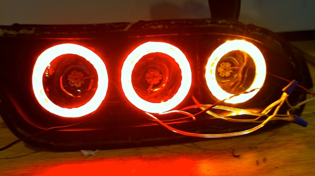
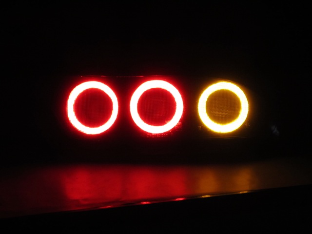
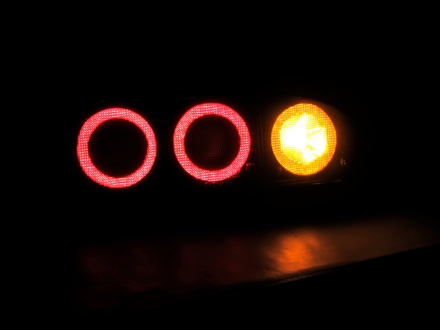
Finally, my original turn signal modification (as shown in the previous pics and videos) has been redesigned. I didn’t like what I originally had, so I modified the turn signals to use both amber rings as well as a center turn signal light. The amber rings turn on when the parking lights come on and the center section activates with the turn signals.
Here is a pic of the new design:
Parking Lights On:
Parking Lights With Turn Signal On:
Parking Lights With Brakes On:

For me, the units are now safe, are made with superior LEDs and materials, the wiring has been upgraded, and the units have proper heat sink and thermal management. And yes, I did all of the redesign and fabrication myself which means you can do this too.
Project Cost and Parts List
The total cost for completely redoing both taillight assemblies was $388.40. This includes all new materials and also the cost of any miscellaneous parts such as glue and adhesives. If these were to be mass-produced, the materials cost would be under $300 per set of lights as LED manufacturers offer attractive quantity discounts and the miscellaneous parts cost would be spread out over for many sets of lights.
For those that already have the Theorie conversion and wish to only upgrade the brake lights, the total cost would be around $150. You’d only need to add the center brake light into the assembly. If you choose to do this, I also recommend you rewire the 60 mm LED ring into the parking lights so it comes on with the parking lights. By doing this and then by also modifying the acrylic rings as described later, you will greatly increase the brightness of the parking lights at no additional cost.
Summary:
Total Cost of Project: $388.40
Total LED Cost Per Taillight Assembly: $167.94
Miscellaneous Parts: $52.52
Here is a parts list for all of the components used.
Taillight Assembly Components
Parking Light and Turn Signal LED Ring Components
From www.superbrightleds.com
Parking Light Red Rings
(2) AE80-R24: 80mm Diameter Red LED Angel Eye Headlight Accent Lights
http://www.superbrightleds.com/cgi-b...2Fpt%2Fae.html
Cost: $7.95 per unit, total cost: $15.90
(2) AE60-R15: 60mm Diameter Red LED Angel Eye Headlight Accent Lights
http://www.superbrightleds.com/cgi-b...2Fpt%2Fae.html
Cost: $5.95 per unit, total cost: $11.90
Turn Signal Amber Ring
(1) AE80-A24: 80mm Diameter Amber LED Angel Eye Headlight Accent Lights
http://www.superbrightleds.com/cgi-b...2Fpt%2Fae.html
Cost: $7.95 per unit, total cost: $7.95
(1) AE60-A15: 60mm Diameter Amber LED Angel Eye Headlight Accent Lights
http://www.superbrightleds.com/cgi-b...2Fpt%2Fae.html
Cost: $5.95 per unit, total cost: $5.95
(1) RL-2525 Marker Lamp Load Resistor
http://www.superbrightleds.com/cgi-b...html%23flasher
Cost: $3.95 per unit, total cost: $3.95
Total Cost of Parking Light and Turn Signal LED Ring Components: $45.65
Brake Lights and Turn Signal Components
From www.luxeonstar.com
Brake Lights
(2) Red-Orange (617 nm) Rebel LED, Pre-Mounted On A 20mm Tri-Star Base - 366 lm @ 700mA
http://www.luxeonstar.com/Red-Orange...-h2060-20t.htm
Cost: $15.00 per unit, total cost: $30.00
(2) Heat Sinks 40mm Round x 20mm High Alpha Heat Sink - 9.5 �C/W
http://www.luxeonstar.com/40mm-Round...p/cn40-20b.htm
Cost: $6.68 per unit, total cost: $13.36
(1) Pre-Cut, Thermal Adhesive Tape for 20mm Hex Bases (12 Piece Sheet): Includes enough for both taillights
http://www.luxeonstar.com/Pre-Cut-Th...p/lxt-s-12.htm
Cost: $7.49 per unit, total cost: $7.49
(1) 700mA, Internally Dimmable, BuckPuck DC Driver - PCB Mount
http://www.luxeonstar.com/700mA-Int-...21-d-i-700.htm
Cost: $20.99 per unit, total cost: $20.99
(1) Wiring Harness for 3021 & 4015 'N' Drivers - 4 wire
http://www.luxeonstar.com/Wiring-Har...s-p/3021hn.htm
Cost: $3.49 per unit, total cost: $3.49
Turn Signals
(1) Amber (590 nm) Rebel LED, Pre-Mounted On A 20mm Tri-Star Base - 231 lm @ 700mA
http://www.luxeonstar.com/Amber-590-...-l0040-20t.htm
Cost: $15.80 per unit, total cost: $15.80
(1) Heat Sink 40mm Round x 20mm High Alpha Heat Sink - 9.5 �C/W
http://www.luxeonstar.com/40mm-Round...p/cn40-20b.htm
Cost: $6.68 per unit, total cost: $6.68
(1) 700mA, Internally Dimmable, BuckPuck DC Driver - PCB Mount
http://www.luxeonstar.com/700mA-Int-...21-d-i-700.htm
Cost: $20.99 per unit, total cost: $20.99
(1) Wiring Harness for 3021 & 4015 'N' Drivers - 4 wire
http://www.luxeonstar.com/Wiring-Har...s-p/3021hn.htm
Cost: $3.49 per unit, total cost: $3.49
Total Cost of Brake Light and Turn Signal Components: $122.29
Miscellaneous Parts: Total Cost - $52.52
Metal and Acrylic
(2) MD Building Products 1 ft. x 1 ft. Aluminum Sheet
http://www.homedepot.com/h_d1/N-5yc1...atalogId=10053
Cost: $7.47 per unit, total cost: $14.94
(1) OPTIX 36 in. x 30 in. x .093 Acrylic Sheet
http://www.homedepot.com/Building-Ma...kuId=202939033
Cost: $21.98 per unit, total cost: $21.98
Glue/Adhesives
(1) Permatex/3.35 oz. (95 g.) tube Ultra Black maximum oil resistance RTV silicone gasket maker
http://www.autozone.com/autozone/acc...er=554295_0_0_
Cost: $6.99 per unit, total cost: $6.99
(1) Loctite Stik'N Seal 0.58 fl. oz. Ultra Universal Adhesive
http://www.homedepot.com/h_d1/N-5yc1...1&ddkey=Search
Cost: $5.67 per unit, total cost: $5.67
Empty Socket Bases from www.superbrightleds.com:
http://www.superbrightleds.com/cgi-b...rake-turn.html
Turn Signals
(2) BA15S-EB: BA15S Empty BA15 base
Cost: $0.49 per unit, total cost: $0.98
Brake Lights
(4) BAY15D-EB: BAY15D Empty BA15 Base
Cost: $0.49 per unit, total cost: $1.96
Hello! I have been asked many times to describe what I did to modify my set of lights. I have now completed the project and here are the details. Use what I have done in any way you wish. If you want to take this and offer it as a commercial product, have at it.
First, the light output is outstanding. See previously posted pics and videos for comparisons. My goal with every LED project is to get brighter light than stock output and this has been achieved with the modifications. As previously posted (#68), the results versus the Theorie LEDs are:
17X brighter than the parking lights
32X brighter than the brake lights, and
16X brighter than the turn signals
Remember, to make the newly modified lights equal in brightness to the OEM units, the new design needed to be at least 5X brighter than the Theorie parking lights and about 25X brighter than the brake lights. This has been achieved. The brake lights have been “turned down” so they are less bright than before (now 32 times brighter than the Theorie units versus the previous 52X). This is possible through the use of an internal dimmer built into the LED “drivers” that allows for adjustment of the brightness of the units (from 40 - 110%). I turned the brightness down so the new design is slightly above the output of my old www.superbrightleds.com LED brake bulbs or roughly 175% of the stock units. If you disagree with the light output level I used, you can set your own to any level you desire. Also, if these were mass-produced, the manufacturer could dial in the desired level and then seal up the units, preventing the customer from altering the level.
Finally, my original turn signal modification (as shown in the previous pics and videos) has been redesigned. I didn’t like what I originally had, so I modified the turn signals to use both amber rings as well as a center turn signal light. The amber rings turn on when the parking lights come on and the center section activates with the turn signals.
Here is a pic of the new design:
Parking Lights On:
Parking Lights With Turn Signal On:
Parking Lights With Brakes On:
For me, the units are now safe, are made with superior LEDs and materials, the wiring has been upgraded, and the units have proper heat sink and thermal management. And yes, I did all of the redesign and fabrication myself which means you can do this too.
Project Cost and Parts List
The total cost for completely redoing both taillight assemblies was $388.40. This includes all new materials and also the cost of any miscellaneous parts such as glue and adhesives. If these were to be mass-produced, the materials cost would be under $300 per set of lights as LED manufacturers offer attractive quantity discounts and the miscellaneous parts cost would be spread out over for many sets of lights.
For those that already have the Theorie conversion and wish to only upgrade the brake lights, the total cost would be around $150. You’d only need to add the center brake light into the assembly. If you choose to do this, I also recommend you rewire the 60 mm LED ring into the parking lights so it comes on with the parking lights. By doing this and then by also modifying the acrylic rings as described later, you will greatly increase the brightness of the parking lights at no additional cost.
Summary:
Total Cost of Project: $388.40
Total LED Cost Per Taillight Assembly: $167.94
Miscellaneous Parts: $52.52
Here is a parts list for all of the components used.
Taillight Assembly Components
Parking Light and Turn Signal LED Ring Components
From www.superbrightleds.com
Parking Light Red Rings
(2) AE80-R24: 80mm Diameter Red LED Angel Eye Headlight Accent Lights
http://www.superbrightleds.com/cgi-b...2Fpt%2Fae.html
Cost: $7.95 per unit, total cost: $15.90
(2) AE60-R15: 60mm Diameter Red LED Angel Eye Headlight Accent Lights
http://www.superbrightleds.com/cgi-b...2Fpt%2Fae.html
Cost: $5.95 per unit, total cost: $11.90
Turn Signal Amber Ring
(1) AE80-A24: 80mm Diameter Amber LED Angel Eye Headlight Accent Lights
http://www.superbrightleds.com/cgi-b...2Fpt%2Fae.html
Cost: $7.95 per unit, total cost: $7.95
(1) AE60-A15: 60mm Diameter Amber LED Angel Eye Headlight Accent Lights
http://www.superbrightleds.com/cgi-b...2Fpt%2Fae.html
Cost: $5.95 per unit, total cost: $5.95
(1) RL-2525 Marker Lamp Load Resistor
http://www.superbrightleds.com/cgi-b...html%23flasher
Cost: $3.95 per unit, total cost: $3.95
Total Cost of Parking Light and Turn Signal LED Ring Components: $45.65
Brake Lights and Turn Signal Components
From www.luxeonstar.com
Brake Lights
(2) Red-Orange (617 nm) Rebel LED, Pre-Mounted On A 20mm Tri-Star Base - 366 lm @ 700mA
http://www.luxeonstar.com/Red-Orange...-h2060-20t.htm
Cost: $15.00 per unit, total cost: $30.00
(2) Heat Sinks 40mm Round x 20mm High Alpha Heat Sink - 9.5 �C/W
http://www.luxeonstar.com/40mm-Round...p/cn40-20b.htm
Cost: $6.68 per unit, total cost: $13.36
(1) Pre-Cut, Thermal Adhesive Tape for 20mm Hex Bases (12 Piece Sheet): Includes enough for both taillights
http://www.luxeonstar.com/Pre-Cut-Th...p/lxt-s-12.htm
Cost: $7.49 per unit, total cost: $7.49
(1) 700mA, Internally Dimmable, BuckPuck DC Driver - PCB Mount
http://www.luxeonstar.com/700mA-Int-...21-d-i-700.htm
Cost: $20.99 per unit, total cost: $20.99
(1) Wiring Harness for 3021 & 4015 'N' Drivers - 4 wire
http://www.luxeonstar.com/Wiring-Har...s-p/3021hn.htm
Cost: $3.49 per unit, total cost: $3.49
Turn Signals
(1) Amber (590 nm) Rebel LED, Pre-Mounted On A 20mm Tri-Star Base - 231 lm @ 700mA
http://www.luxeonstar.com/Amber-590-...-l0040-20t.htm
Cost: $15.80 per unit, total cost: $15.80
(1) Heat Sink 40mm Round x 20mm High Alpha Heat Sink - 9.5 �C/W
http://www.luxeonstar.com/40mm-Round...p/cn40-20b.htm
Cost: $6.68 per unit, total cost: $6.68
(1) 700mA, Internally Dimmable, BuckPuck DC Driver - PCB Mount
http://www.luxeonstar.com/700mA-Int-...21-d-i-700.htm
Cost: $20.99 per unit, total cost: $20.99
(1) Wiring Harness for 3021 & 4015 'N' Drivers - 4 wire
http://www.luxeonstar.com/Wiring-Har...s-p/3021hn.htm
Cost: $3.49 per unit, total cost: $3.49
Total Cost of Brake Light and Turn Signal Components: $122.29
Miscellaneous Parts: Total Cost - $52.52
Metal and Acrylic
(2) MD Building Products 1 ft. x 1 ft. Aluminum Sheet
http://www.homedepot.com/h_d1/N-5yc1...atalogId=10053
Cost: $7.47 per unit, total cost: $14.94
(1) OPTIX 36 in. x 30 in. x .093 Acrylic Sheet
http://www.homedepot.com/Building-Ma...kuId=202939033
Cost: $21.98 per unit, total cost: $21.98
Glue/Adhesives
(1) Permatex/3.35 oz. (95 g.) tube Ultra Black maximum oil resistance RTV silicone gasket maker
http://www.autozone.com/autozone/acc...er=554295_0_0_
Cost: $6.99 per unit, total cost: $6.99
(1) Loctite Stik'N Seal 0.58 fl. oz. Ultra Universal Adhesive
http://www.homedepot.com/h_d1/N-5yc1...1&ddkey=Search
Cost: $5.67 per unit, total cost: $5.67
Empty Socket Bases from www.superbrightleds.com:
http://www.superbrightleds.com/cgi-b...rake-turn.html
Turn Signals
(2) BA15S-EB: BA15S Empty BA15 base
Cost: $0.49 per unit, total cost: $0.98
Brake Lights
(4) BAY15D-EB: BAY15D Empty BA15 Base
Cost: $0.49 per unit, total cost: $1.96
Last edited by RENESISFD; 08-06-12 at 06:29 AM.
Trending Topics
11-02-11, 10:42 PM
#8
Metal Component Templates
Why replace the metal? The metal is an integral part of the structure and I was not comfortable with the Theorie juice and soda can stock holding up over time as for me, the stock used was too thin and I felt the tape holding it together would not last.
I have templates for all metal pieces used in the conversion. These templates include the:
- Outer brake ring
- Brake light reflector
- Turn signal ring
- Turn signal reflector
- Back plates
The templates can be found here:
http://gallery.me.com/david.hayes#100056
Although I used stainless steel stock purchased from Ace Hardware, any aluminum stock such as what I have included in the parts list will work.
Acrylic Ring Templates
The modified LED units use CLEAR acrylic rings instead of the OPAQUE rings used in the Theorie conversion. Why use CLEAR rings? Because they greatly increase the light output without affecting the design.
I did extensive testing of the Theorie units to determine why the light output was so low. In my testing, I found the OPAQUE acrylic rings used by Theorie negatively affected the light output. For example, when testing the parking lights, the Theorie LED rings tested at 248 lux with the Theorie acrylic ring. By using a clear acrylic ring, light output improved to 1,182 lux. This represents an increase of over 377% in light output by simply using a clear ring versus the opaque ring.
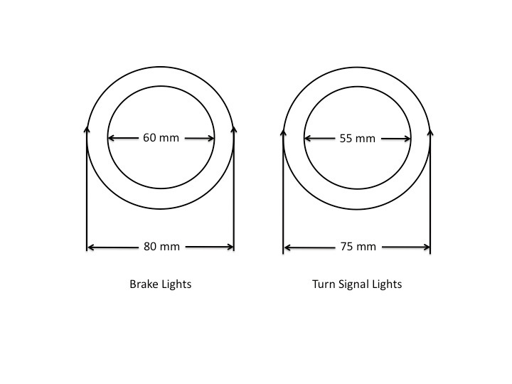
Here are the dimensions for the acrylic rings. The brake rings are slightly larger than the turn signal rings due to the difference in sizes of the 99 spec conversions:
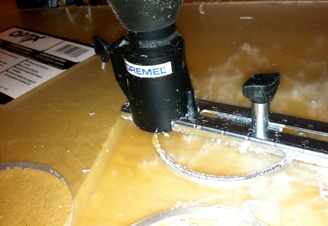
I used a Dremel circle cutter, which worked great, to make these:
http://www.google.com/products/catal...wAA#ps-sellers
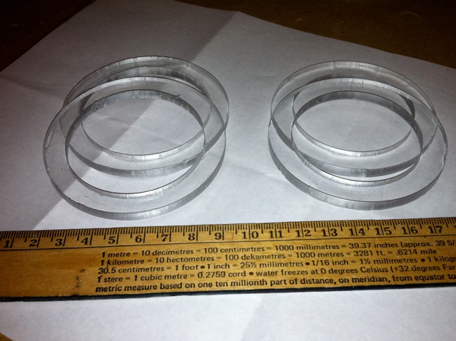
Here are pics of the acrylic rings I fabricated with the Dremel:
** A note on cutting the acrylic rings **
Cut the outer circle first and then the inner circle. Once you've cut the outer circle you can then cut the inner circle by simply holding and rotating the acrylic. Be careful with the last bit of cut as there is nothing to support the circle. Try one and you'll see what I mean.
The Dremel drill bit has an outer and inner edge so when you make a circle, you will need to account for the thickness of the bit. For outer circle cuts, set the device so the inside of the bit edge is at the desired dimension. So for 80 mm rings, set the inside of the bit at 80 mm. For inside circle cuts, set the outside of the bit to the desired dimension.
You can use the bit to help smooth out an outside circle cut by simply rotating the circle still on the Dremel after you've cut the circle. By doing this you use the Dremel to clean up the outside edge. I used a Dremel sanding attachment to clean up the inside edges.
Finally, I found it was best to make all Dremel cuts with the acrylic stock material raised up and off of the surface. This gives the Dremel room for the waste cut material to drop below the ring and not get caught up in the circle cut.
LED Information
Two notes. First, the color of the LEDs used must match the color of the taillight lens (see my parts list – the list includes color matched LEDs). For example, the FD brake light lens is red. Therefore, use red LEDs. The turn signal lens is amber so use amber LEDs. This is LED “modification 101” and is a primary reason a lot of people see low light output when swapping out stock bulbs for LED units. They use white bulbs when they should use red or amber.
Why is this a must? Because LEDs operate differently than normal incandescent bulbs. Where a normal incandescent bulb produces a light that includes a full spectrum of color, white LEDs “fool” the eye into seeing white by blending together several colors of light and when placed behind a colored plastic lens, the lens will filter out all light except the color of the lens. So for the brake lights, the red lens will filter out all color except red and the amber turn signal lens will only allow amber to pass through the lens. In short, you must match the color of your LEDs to the color of the lens or you will not be pleased.
From the www.superbrightleds.com website:
“Which Color LEDs should I use?
For best results the LED color should be the same as the lens color or if bulb is behind a clear lens, use the appropriate color for turn and brake light functions. As an example: a red lens will filter out all but the red portion of the light so if the light is all red, none or very little light will be blocked by the lens. The light from a White LED contains very little light in the red portion of the visible spectrum so most of the light would be filtered out by a red lens.”
From a second source:
“The LED color and the VEHICLE lens color must match. Either use a clear lens or match the color of the LED with the lens. Using an LED colored differently than the lens color will greatly reduce the light output and reduce the effectiveness of the light for emergency signaling purposes.”
What does this mean in real life? The Theorie LED conversion used white LEDs behind a red lens for the brakes, resulting in a very large loss of light output. How much? When testing a Theorie parking light ring, the assembly produces 1,182 lux, which is a good amount of light. However, when placed behind a red lens, the unit tests at 47 lux, representing a loss of over 96% of the total light output. Not good.
By using the same technology (3528 SMD LED rings) but substituting RED LED rings instead of the white LED rings for the brakes, light output is significantly increased. A single red LED ring behind a red lens tests at 180 lux, over 3X higher than the 47 lux of the white LEDs. And when then combined with activating both the 80 mm and the 60 mm LED rings for the parking lights (compared to the one 80 mm ring used in the Theorie conversion) and by using CLEAR instead of OPAQUE acrylic rings, total parking light output is increased by 17 X, making the new design brighter than OEM lights.
A second LED note – LED “rings’ should not be used for brake lights. These rings are normally used for “angel eye” applications and do not produce enough light, regardless of color, to be used effectively as a safety warning light in brake applications. Testing is conclusive on this. Brake lights have one purpose, to warn those behind that you are braking. I also don’t believe LED rings are bright enough for turn signal applications which is why I replaced them there also. A better solution than LED rings is needed.
What is that solution? For me it is the use of high-powered circuit mounted LEDs such as the ones included in the parts list. By using this style LED you can be assured of superior light output as well as units that will stand up to use over time. For this project I tested several different style LEDs and found the ones I have recommended to be the easiest to wire up as well as to have the brightest light output. A win-win combination.
Why replace the metal? The metal is an integral part of the structure and I was not comfortable with the Theorie juice and soda can stock holding up over time as for me, the stock used was too thin and I felt the tape holding it together would not last.
I have templates for all metal pieces used in the conversion. These templates include the:
- Outer brake ring
- Brake light reflector
- Turn signal ring
- Turn signal reflector
- Back plates
The templates can be found here:
http://gallery.me.com/david.hayes#100056
Although I used stainless steel stock purchased from Ace Hardware, any aluminum stock such as what I have included in the parts list will work.
Acrylic Ring Templates
The modified LED units use CLEAR acrylic rings instead of the OPAQUE rings used in the Theorie conversion. Why use CLEAR rings? Because they greatly increase the light output without affecting the design.
I did extensive testing of the Theorie units to determine why the light output was so low. In my testing, I found the OPAQUE acrylic rings used by Theorie negatively affected the light output. For example, when testing the parking lights, the Theorie LED rings tested at 248 lux with the Theorie acrylic ring. By using a clear acrylic ring, light output improved to 1,182 lux. This represents an increase of over 377% in light output by simply using a clear ring versus the opaque ring.
Here are the dimensions for the acrylic rings. The brake rings are slightly larger than the turn signal rings due to the difference in sizes of the 99 spec conversions:
I used a Dremel circle cutter, which worked great, to make these:
http://www.google.com/products/catal...wAA#ps-sellers
Here are pics of the acrylic rings I fabricated with the Dremel:
** A note on cutting the acrylic rings **
Cut the outer circle first and then the inner circle. Once you've cut the outer circle you can then cut the inner circle by simply holding and rotating the acrylic. Be careful with the last bit of cut as there is nothing to support the circle. Try one and you'll see what I mean.
The Dremel drill bit has an outer and inner edge so when you make a circle, you will need to account for the thickness of the bit. For outer circle cuts, set the device so the inside of the bit edge is at the desired dimension. So for 80 mm rings, set the inside of the bit at 80 mm. For inside circle cuts, set the outside of the bit to the desired dimension.
You can use the bit to help smooth out an outside circle cut by simply rotating the circle still on the Dremel after you've cut the circle. By doing this you use the Dremel to clean up the outside edge. I used a Dremel sanding attachment to clean up the inside edges.
Finally, I found it was best to make all Dremel cuts with the acrylic stock material raised up and off of the surface. This gives the Dremel room for the waste cut material to drop below the ring and not get caught up in the circle cut.
LED Information
Two notes. First, the color of the LEDs used must match the color of the taillight lens (see my parts list – the list includes color matched LEDs). For example, the FD brake light lens is red. Therefore, use red LEDs. The turn signal lens is amber so use amber LEDs. This is LED “modification 101” and is a primary reason a lot of people see low light output when swapping out stock bulbs for LED units. They use white bulbs when they should use red or amber.
Why is this a must? Because LEDs operate differently than normal incandescent bulbs. Where a normal incandescent bulb produces a light that includes a full spectrum of color, white LEDs “fool” the eye into seeing white by blending together several colors of light and when placed behind a colored plastic lens, the lens will filter out all light except the color of the lens. So for the brake lights, the red lens will filter out all color except red and the amber turn signal lens will only allow amber to pass through the lens. In short, you must match the color of your LEDs to the color of the lens or you will not be pleased.
From the www.superbrightleds.com website:
“Which Color LEDs should I use?
For best results the LED color should be the same as the lens color or if bulb is behind a clear lens, use the appropriate color for turn and brake light functions. As an example: a red lens will filter out all but the red portion of the light so if the light is all red, none or very little light will be blocked by the lens. The light from a White LED contains very little light in the red portion of the visible spectrum so most of the light would be filtered out by a red lens.”
From a second source:
“The LED color and the VEHICLE lens color must match. Either use a clear lens or match the color of the LED with the lens. Using an LED colored differently than the lens color will greatly reduce the light output and reduce the effectiveness of the light for emergency signaling purposes.”
What does this mean in real life? The Theorie LED conversion used white LEDs behind a red lens for the brakes, resulting in a very large loss of light output. How much? When testing a Theorie parking light ring, the assembly produces 1,182 lux, which is a good amount of light. However, when placed behind a red lens, the unit tests at 47 lux, representing a loss of over 96% of the total light output. Not good.
By using the same technology (3528 SMD LED rings) but substituting RED LED rings instead of the white LED rings for the brakes, light output is significantly increased. A single red LED ring behind a red lens tests at 180 lux, over 3X higher than the 47 lux of the white LEDs. And when then combined with activating both the 80 mm and the 60 mm LED rings for the parking lights (compared to the one 80 mm ring used in the Theorie conversion) and by using CLEAR instead of OPAQUE acrylic rings, total parking light output is increased by 17 X, making the new design brighter than OEM lights.
A second LED note – LED “rings’ should not be used for brake lights. These rings are normally used for “angel eye” applications and do not produce enough light, regardless of color, to be used effectively as a safety warning light in brake applications. Testing is conclusive on this. Brake lights have one purpose, to warn those behind that you are braking. I also don’t believe LED rings are bright enough for turn signal applications which is why I replaced them there also. A better solution than LED rings is needed.
What is that solution? For me it is the use of high-powered circuit mounted LEDs such as the ones included in the parts list. By using this style LED you can be assured of superior light output as well as units that will stand up to use over time. For this project I tested several different style LEDs and found the ones I have recommended to be the easiest to wire up as well as to have the brightest light output. A win-win combination.
Last edited by RENESISFD; 08-06-12 at 06:31 AM.
11-02-11, 10:43 PM
#9
Fabrication of the LED Units
Tools Required:
- heat gun: to remove the plastic clear lens cover off of the taillight assemblies
- regular screwdriver: to remove the brake and turn signal OEM inside lenses
- metal sheers: for cutting the metal rings and reflectors
- riveter: to hold together the new metal rings and reflectors
- soldering iron: for wiring up the lights
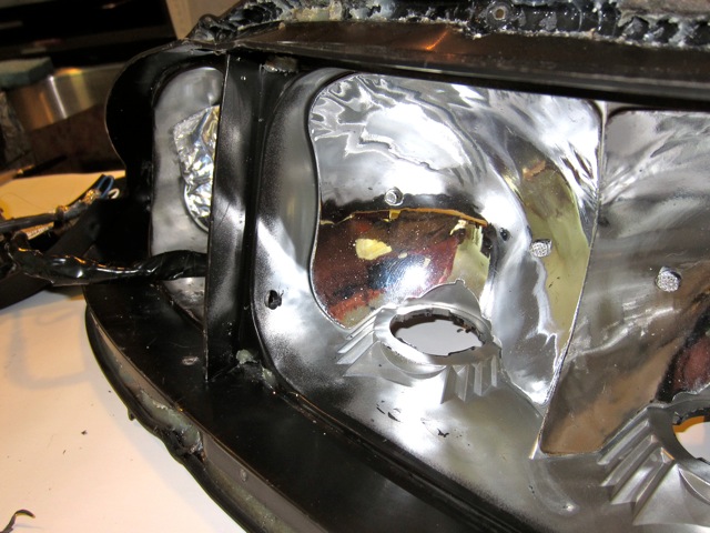
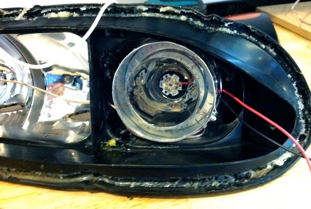
You’ll first need to take apart the taillight assemblies. You do this by removing the 6 screws on the backside of the OEM taillight plastic housing. You then apply heat to the outer back edge of the taillight where the back meets the front clear cover to melt the clear adhesive that holds the front lens cover to the back housing. Take your time and it’s easy. I used a hair dryer because my heat gun was in storage and it took me about 10 minutes of applying heat before I was able to separate the lens from the back housing. Set the front lens cover aside for safekeeping.
With the plastic front lens off, you’ll see the tail lamp has two sections, one comprised of two lights and the other made up of the turn signal. Each of these sections is held on with a single screw (on the upper side of the brake section and the bottom corner of the turn signal) that needs to be removed. Once you have done this, look along the top lip on the right of the brake section and on the left of the turn signal assembly to locate the small tab that secures each section. Use a screwdriver to unclip the tab and pull each section out. There will be some resistance here as each section is also held on with a small amount of clear adhesive.
With this done, you’ll see each taillight is comprised of three light sections, two for the brakes and one for the turn signals. The two new brake LED assemblies are identical 80mm units and the turn signal is a slightly smaller 75 mm size. The size differences correspond to the sizes of the 99 spec brake lights and turn signals.
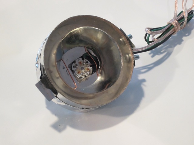
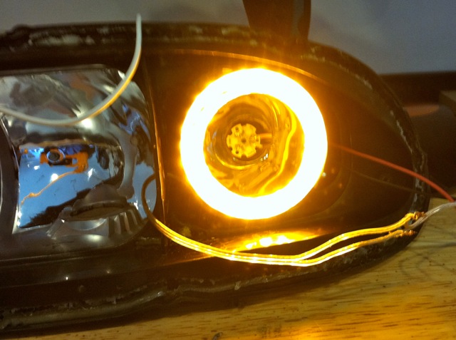
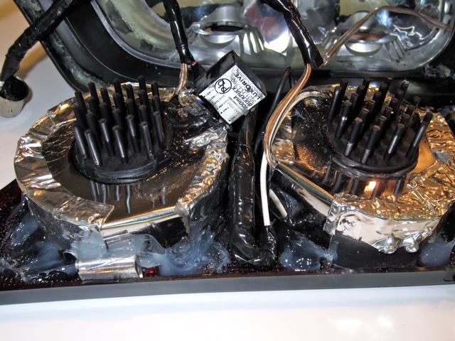
Here are pics of a modified LED brake light unit:
Front of Unit (faces red lens):
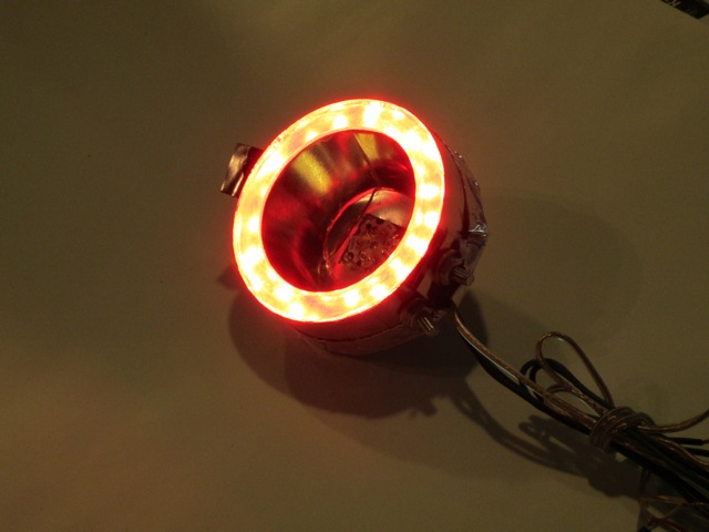
And with the parking lights on:
In the middle is a reflector and a high-powered LED circuit mounted component and if you look through the acrylic ring, you can see the 80 and the 60 mm LED rings. For the center reflector, the test unit was glued together using Loctite Stik'N Seal Ultra Universal Adhesive. For the final versions, I also riveted the reflector together. The outer ring in the pic is glued and screwed together but the screws were replaced with rivets as well.
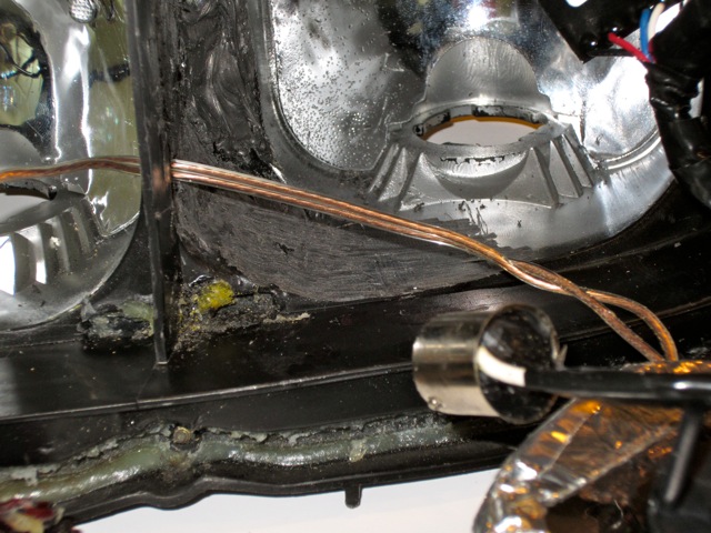
Back of Unit:
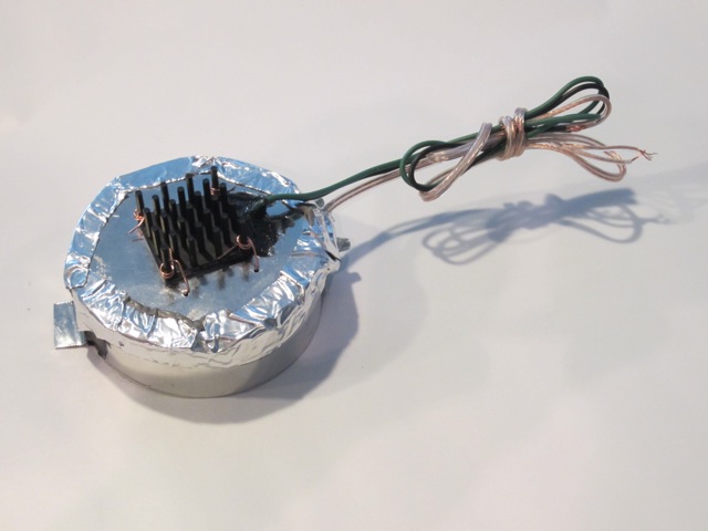
The back of the unit contains the thermal heat sink for the high-powered brake and turn signal LEDs. The heat sink attaches to a back plate (which you will make following the template) with either thermal adhesive glue or with high temp RTV. Either works just fine. I also then used copper wire to attach the heat sink to the back plate for an extra level of security. The silver tape is Home Depot tape that holds the back plate to the round light housings. You could glue this on or use silicone or tape it on. I did both.
Each light assembly is made up of the following:
(1) outside metal ring – see template
(1) inner light metal reflector – see template
(1) metal back plate – see template
(1) acrylic clear ring – 80 mm for the brakes and 75 mm for the turn signals – see templates
(1) high-powered center circuit mounted LED – see parts list
(1) heat sink for high-powered LED – see parts list
(1) 80 mm led ring – red for brakes and amber for turn signal – see parts list
(1) 60 mm led ring – red for brakes and amber for turn signal – see parts list
To fabricate an assembly, use the provided templates to fabricate the acrylic rings and the metal components. See previous pics.
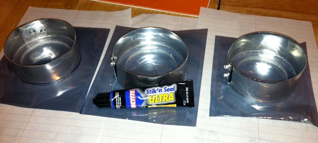
Next, “wrap” the outside metal rings around the two 80 mm acrylic rings and the one 75 mm ring to form the outer housings for the light units. Note there is a separate outer metal housing template for the 75 mm unit. The template for this has one straight side and one curved side. When formed as a circle, the curved side will be placed turn signal lens down resulting in the metal housing being at an angle which will assit in clearing the sides of the OEM back plastic housing. When properly turned, the unit will turn away from the inside wall of the housing. Next, use adhesive and rivets to hold the outer metal rings together. Finally, use adhesive to glue the acrylic rings into the inside front of the metal housings. Here is a pic of the completed outer metal housings and the acrylic rings. The two housings on the left are for the 80 mm brake units and the one on the right is the 75 mm turn signal unit:
Now form the reflectors for each unit using the templates provided. The reflectors sit in the inside of the acrylic rings and get glued to the ring. Take your time hand forming these and use the rings as a guide. I ended up using glue and a rivet gun once I had the shape formed out. I also trimmed them slightly on the side facing away from the high-powered LEDs, which should sit on top of the reflector with the LED positioned in the middle of the hole in the reflector. See the pics as a guide for what this should look like.
Tools Required:
- heat gun: to remove the plastic clear lens cover off of the taillight assemblies
- regular screwdriver: to remove the brake and turn signal OEM inside lenses
- metal sheers: for cutting the metal rings and reflectors
- riveter: to hold together the new metal rings and reflectors
- soldering iron: for wiring up the lights
You’ll first need to take apart the taillight assemblies. You do this by removing the 6 screws on the backside of the OEM taillight plastic housing. You then apply heat to the outer back edge of the taillight where the back meets the front clear cover to melt the clear adhesive that holds the front lens cover to the back housing. Take your time and it’s easy. I used a hair dryer because my heat gun was in storage and it took me about 10 minutes of applying heat before I was able to separate the lens from the back housing. Set the front lens cover aside for safekeeping.
With the plastic front lens off, you’ll see the tail lamp has two sections, one comprised of two lights and the other made up of the turn signal. Each of these sections is held on with a single screw (on the upper side of the brake section and the bottom corner of the turn signal) that needs to be removed. Once you have done this, look along the top lip on the right of the brake section and on the left of the turn signal assembly to locate the small tab that secures each section. Use a screwdriver to unclip the tab and pull each section out. There will be some resistance here as each section is also held on with a small amount of clear adhesive.
With this done, you’ll see each taillight is comprised of three light sections, two for the brakes and one for the turn signals. The two new brake LED assemblies are identical 80mm units and the turn signal is a slightly smaller 75 mm size. The size differences correspond to the sizes of the 99 spec brake lights and turn signals.
Here are pics of a modified LED brake light unit:
Front of Unit (faces red lens):
And with the parking lights on:
In the middle is a reflector and a high-powered LED circuit mounted component and if you look through the acrylic ring, you can see the 80 and the 60 mm LED rings. For the center reflector, the test unit was glued together using Loctite Stik'N Seal Ultra Universal Adhesive. For the final versions, I also riveted the reflector together. The outer ring in the pic is glued and screwed together but the screws were replaced with rivets as well.
Back of Unit:
The back of the unit contains the thermal heat sink for the high-powered brake and turn signal LEDs. The heat sink attaches to a back plate (which you will make following the template) with either thermal adhesive glue or with high temp RTV. Either works just fine. I also then used copper wire to attach the heat sink to the back plate for an extra level of security. The silver tape is Home Depot tape that holds the back plate to the round light housings. You could glue this on or use silicone or tape it on. I did both.
Each light assembly is made up of the following:
(1) outside metal ring – see template
(1) inner light metal reflector – see template
(1) metal back plate – see template
(1) acrylic clear ring – 80 mm for the brakes and 75 mm for the turn signals – see templates
(1) high-powered center circuit mounted LED – see parts list
(1) heat sink for high-powered LED – see parts list
(1) 80 mm led ring – red for brakes and amber for turn signal – see parts list
(1) 60 mm led ring – red for brakes and amber for turn signal – see parts list
To fabricate an assembly, use the provided templates to fabricate the acrylic rings and the metal components. See previous pics.
Next, “wrap” the outside metal rings around the two 80 mm acrylic rings and the one 75 mm ring to form the outer housings for the light units. Note there is a separate outer metal housing template for the 75 mm unit. The template for this has one straight side and one curved side. When formed as a circle, the curved side will be placed turn signal lens down resulting in the metal housing being at an angle which will assit in clearing the sides of the OEM back plastic housing. When properly turned, the unit will turn away from the inside wall of the housing. Next, use adhesive and rivets to hold the outer metal rings together. Finally, use adhesive to glue the acrylic rings into the inside front of the metal housings. Here is a pic of the completed outer metal housings and the acrylic rings. The two housings on the left are for the 80 mm brake units and the one on the right is the 75 mm turn signal unit:
Now form the reflectors for each unit using the templates provided. The reflectors sit in the inside of the acrylic rings and get glued to the ring. Take your time hand forming these and use the rings as a guide. I ended up using glue and a rivet gun once I had the shape formed out. I also trimmed them slightly on the side facing away from the high-powered LEDs, which should sit on top of the reflector with the LED positioned in the middle of the hole in the reflector. See the pics as a guide for what this should look like.
Last edited by RENESISFD; 08-06-12 at 06:32 AM.
11-02-11, 10:44 PM
#10
LED Fabrication
To complete each light unit, you�ll need to attach a high-powered LED to a heat sink and then attach it to a back plate. You�ll also need to attach an 80 mm LED ring to a 60 mm ring and then insert the ring assembly into the inside of the back of the housing unit (the acrylic ring is on the front and the 80 and 60 mm ring assembly is on the back, away from the acrylic.
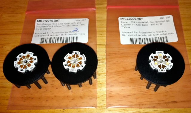
Here is a pic of three high-powered LEDs, two red and one amber, attached to heat sinks. I used Artic Silver Thermal Adhesvie Epoxy to affix the LEDs to the heat sink but the Pre-Cut, Thermal Adhesive Tape for 20mm Hex Bases is a much easier way to get the job done.
You�ll need to pre-wire the high-powered LEDs before going further. The recommended LEDs are by far the easiest I found to wire up. Here is a video link on how to do the job:
http://www.youtube.com/watch?v=R0Df-...layer_embedded
Or from the website:
http://www.luxeonstar.com/Red-Orange...-h2070-20t.htm
See the first video.
I then took each high-powered LED/heat sink/wired unit and affixed it to an 80 mm back metal plate. See the back plate template for this. I cut a hole in the middle of the back plate that was larger than the circuit mounted LED but smaller than the heat sink so I could place the circuit mounted LED in the back plate hole so it would fit/shine through but there would be enough room to use the heat sink to glue it to the back plate.
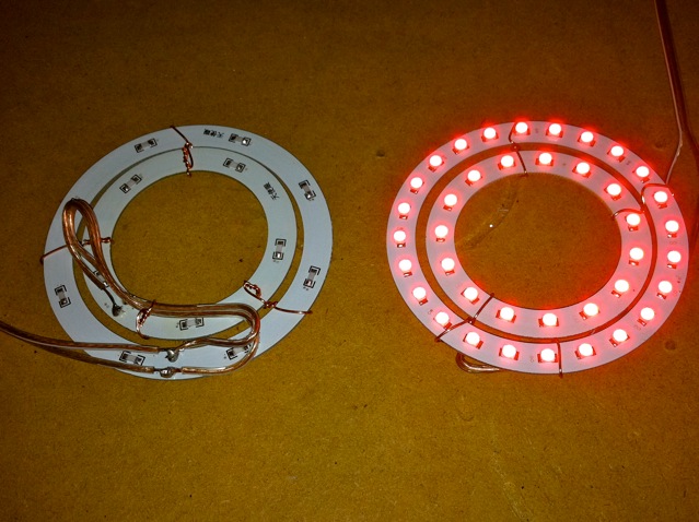
I used plastic coated copper wire to attach the 80 mm LED rings to the 60 mm rings to form one unit. Here is a pic:
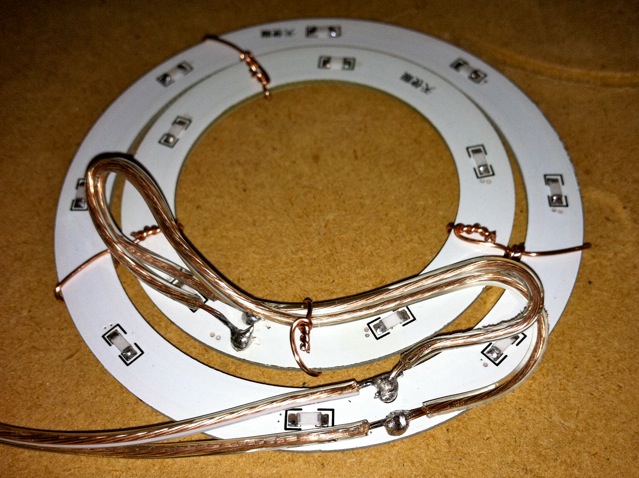
I also replaced the thin wiring that came stock with the LED rings with 22 gauge wire as our FD causes lots of vibrations when driving and I didn�t want the thin wiring to pull loose. Here is a pic of the LED re-wiring with one assembly turned on:
The 80 and 60 mm LED ring unit then gets inserted and glued into the inside of the metal housing and acrylic ring unit (with the LEDs on the rings facing towards the front or towards the acrylic ring). Note the back of each LED ring contains contact points that are live. Should metal touch any of these points, the ring will short out. I recommend you cover these contact points with silicone to eliminate the problem. I used clear silicone for this.
Once the LED ring assembly is inserted, use the high-powered LED back plate assembly to cover over the ring/outer housing/acrylic assembly to form the completed unit. See the previous pics for how a completed unit should look, including using metal tape to hold the back plate on the assembly.
For the 75 mm turn signal assemblies, the 80 and 60 mm LED ring assemblies won�t fit into the inside of the outer metal housings. You�ll just need to place the LED ring assembly over the back of the metal housing and tape it down, ensuring the LEDs on the rings are in the inside of the metal housing. You then affix the high-powered center turn signal LED back plate over this and metal tape down as well.
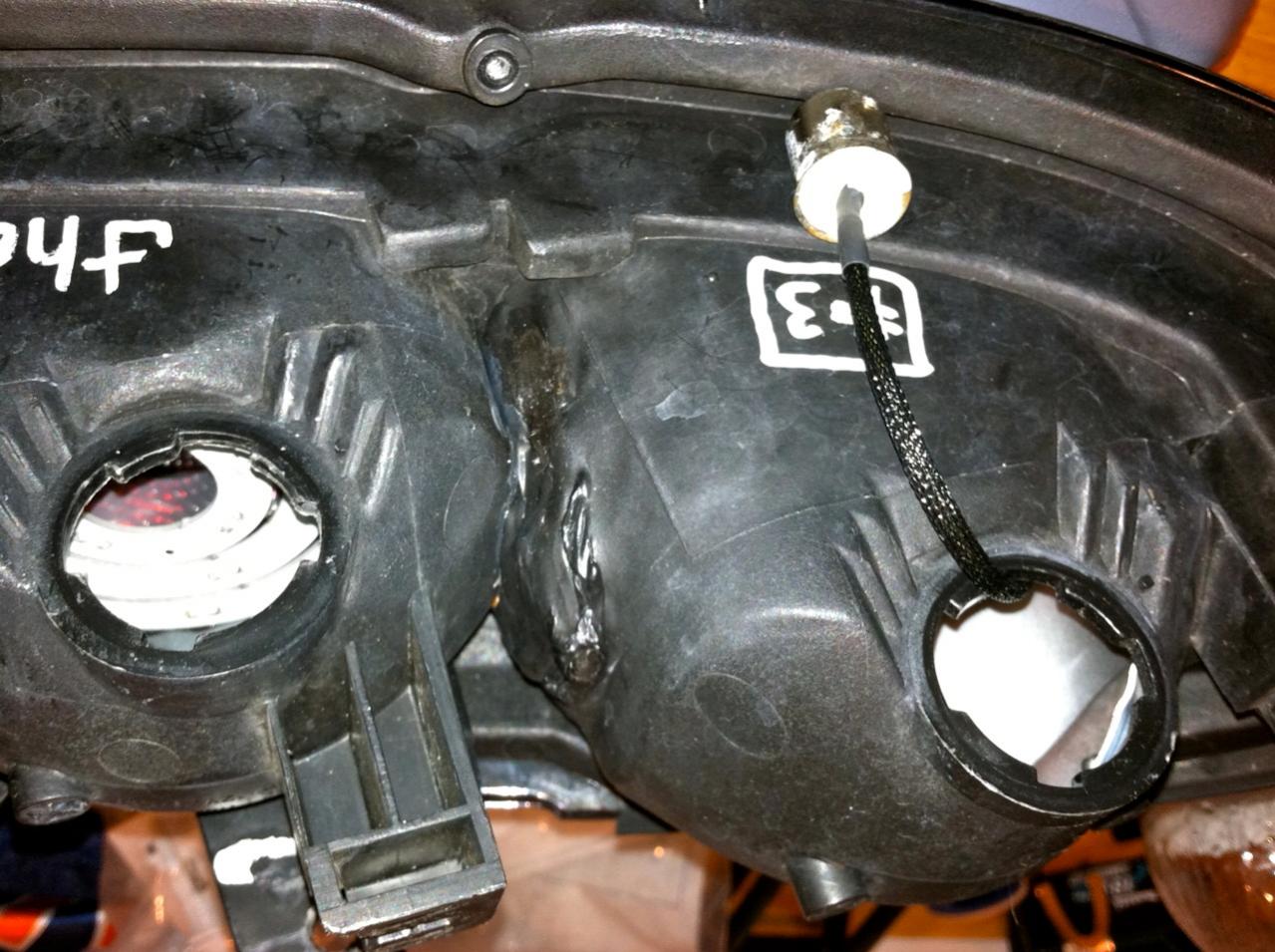
Note to 99 spec owners that do not have the Theorie conversion � to get the turn lamp assemblies to fit properly into the turn lamp back plastic housing, you need to create more space on the inside wall section of each back plastic housing. In short, you need to push out the inside back section and make it flat so the turn signal assembly can slide in. Theorie accomplished this by using a heat gun to heat up the back black plastic until it was pliable enough to manipulate out. I suggest using a flat dry wall blade for this task. Be careful though, if you rush this you�ll end up pushing through the plastic and it will need to be repaired or it will allow in condensation. Your work should end up looking like this:
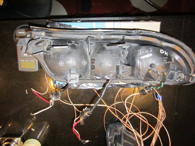
See the right housing with the "DH" on it? The modified section is the left side of the housing. It has been flattened and widened out to the left, or toward the other housings. This gives the turn lamp assembly enough room to slide in. But don't rush this process or you'll end up with this
To complete each light unit, you�ll need to attach a high-powered LED to a heat sink and then attach it to a back plate. You�ll also need to attach an 80 mm LED ring to a 60 mm ring and then insert the ring assembly into the inside of the back of the housing unit (the acrylic ring is on the front and the 80 and 60 mm ring assembly is on the back, away from the acrylic.
Here is a pic of three high-powered LEDs, two red and one amber, attached to heat sinks. I used Artic Silver Thermal Adhesvie Epoxy to affix the LEDs to the heat sink but the Pre-Cut, Thermal Adhesive Tape for 20mm Hex Bases is a much easier way to get the job done.
You�ll need to pre-wire the high-powered LEDs before going further. The recommended LEDs are by far the easiest I found to wire up. Here is a video link on how to do the job:
http://www.youtube.com/watch?v=R0Df-...layer_embedded
Or from the website:
http://www.luxeonstar.com/Red-Orange...-h2070-20t.htm
See the first video.
I then took each high-powered LED/heat sink/wired unit and affixed it to an 80 mm back metal plate. See the back plate template for this. I cut a hole in the middle of the back plate that was larger than the circuit mounted LED but smaller than the heat sink so I could place the circuit mounted LED in the back plate hole so it would fit/shine through but there would be enough room to use the heat sink to glue it to the back plate.
I used plastic coated copper wire to attach the 80 mm LED rings to the 60 mm rings to form one unit. Here is a pic:
I also replaced the thin wiring that came stock with the LED rings with 22 gauge wire as our FD causes lots of vibrations when driving and I didn�t want the thin wiring to pull loose. Here is a pic of the LED re-wiring with one assembly turned on:
The 80 and 60 mm LED ring unit then gets inserted and glued into the inside of the metal housing and acrylic ring unit (with the LEDs on the rings facing towards the front or towards the acrylic ring). Note the back of each LED ring contains contact points that are live. Should metal touch any of these points, the ring will short out. I recommend you cover these contact points with silicone to eliminate the problem. I used clear silicone for this.
Once the LED ring assembly is inserted, use the high-powered LED back plate assembly to cover over the ring/outer housing/acrylic assembly to form the completed unit. See the previous pics for how a completed unit should look, including using metal tape to hold the back plate on the assembly.
For the 75 mm turn signal assemblies, the 80 and 60 mm LED ring assemblies won�t fit into the inside of the outer metal housings. You�ll just need to place the LED ring assembly over the back of the metal housing and tape it down, ensuring the LEDs on the rings are in the inside of the metal housing. You then affix the high-powered center turn signal LED back plate over this and metal tape down as well.
Note to 99 spec owners that do not have the Theorie conversion � to get the turn lamp assemblies to fit properly into the turn lamp back plastic housing, you need to create more space on the inside wall section of each back plastic housing. In short, you need to push out the inside back section and make it flat so the turn signal assembly can slide in. Theorie accomplished this by using a heat gun to heat up the back black plastic until it was pliable enough to manipulate out. I suggest using a flat dry wall blade for this task. Be careful though, if you rush this you�ll end up pushing through the plastic and it will need to be repaired or it will allow in condensation. Your work should end up looking like this:
See the right housing with the "DH" on it? The modified section is the left side of the housing. It has been flattened and widened out to the left, or toward the other housings. This gives the turn lamp assembly enough room to slide in. But don't rush this process or you'll end up with this
11-02-11, 10:45 PM
#11
LED Wiring
To complete the job, you�ll need to wire up the high-powered LED units with LED drivers for the center brake and turn signals and you�ll then need to wire up the LED rings as parking lights.
For each high-powered LED unit, you must use an LED driver or you will blow the assembly. See the parts list for the drivers. You�ll use one 700mA, Internally Dimmable, BuckPuck DC Driver for two brake lights and one 700mA, Internally Dimmable, BuckPuck DC Driver for each turn signal. So, for each taillight, you�ll wire in two LED drivers. Here is a pic of one of the drivers I used:

And a pic of the back of the LED driver:
Note the silver adjustment screw above and to the right of the back label. This is the internal dimming mechanism used to control the output of the center brake and turn signals. You have complete control over how bright the light output is by simply turning the screw. I used this screw adjustment and my light meter to test and adjust down the brightness of the brake lights to a level I felt was bright but would not blind drivers behind me.
For wiring instructions on how to wire up the LED drivers, go here:
http://www.luxeonstar.com/700mA-Int-...21-d-i-700.htm
Click on the �Technical Specifications� link under the �Documentation� section. Or simply look at the wiring labels on the LED driver and attach the positive leads of both high-powered LEDs to the �LED +� and the negatives to the �LED �� on the LED driver. You then wire up the �VIN +� and �VIN �� to a tail lamp positive and negative.
How do you make this so it can plug right into the car? By using the empty BA15 bases included in the parts list to make wires that will plug directly into the OEM tail lamp sockets. For each taillight, the FD uses one �single contact� plug (1156) for the turn signal and then two �dual contact� plugs (1157) for the brake lamps. The dual contact plugs activate one side of the wiring when you turn on the parking lights and then the other side of the socket for the brakes. So, for the turn signals, you�ll use a single contact plug that will have two wires coming out of it, one for a positive and one for a negative. For the brake lights, you�ll wire up two three wire plugs, with each having one negative wire soldered into the inside of the socket housing and then two positive wires, one for the parking lights and then the other positive to activate the brakes.
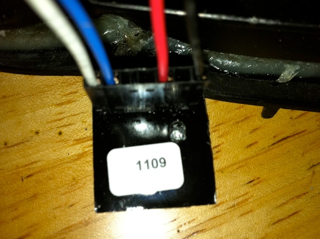
I fabricated up my own wires for this. I used 22-gauge wiring and soldered in the positives and then the one negative soldered into the inside of the socket. Here is what the results look like:

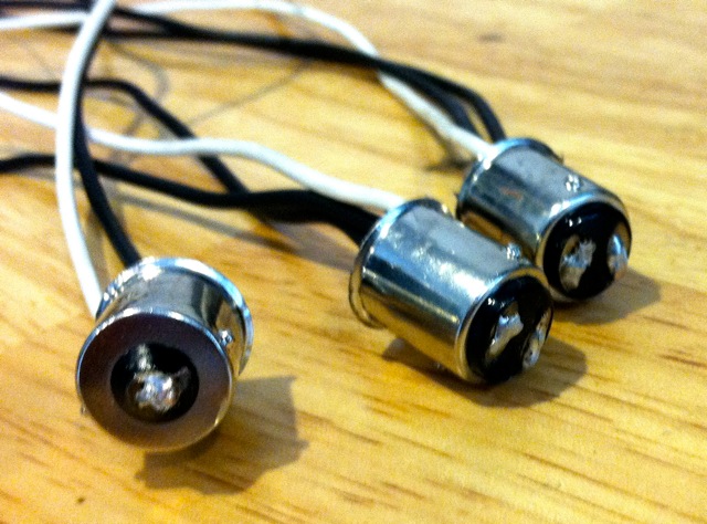
You end up with two three-wire plugs and one two-wire plug for each assembly. I used black RTV high-temp silicone to seal up the �cups� of the plugs and the wires.
Which side of the dual contact 1157 brake socket is used for the high-powered circuit mounted light and which is used for the parking lights?
Here is a pic that should help:
Rotate the 1157 bulb socket toward you so the lower of the two pegs on the outside of the housing is facing you. The higher peg will be away from you. Now look at the bottom of the socket. You�ll wire up the brake lights to the left side of the socket and the parking lights to the right. If you happen to get it backwards, then simply switch the wiring around.
For all bulbs, you�ll have only one negative wire for each assembly that is shared between the parking and the brake lights.
To complete the job, you�ll need to wire up the high-powered LED units with LED drivers for the center brake and turn signals and you�ll then need to wire up the LED rings as parking lights.
For each high-powered LED unit, you must use an LED driver or you will blow the assembly. See the parts list for the drivers. You�ll use one 700mA, Internally Dimmable, BuckPuck DC Driver for two brake lights and one 700mA, Internally Dimmable, BuckPuck DC Driver for each turn signal. So, for each taillight, you�ll wire in two LED drivers. Here is a pic of one of the drivers I used:
And a pic of the back of the LED driver:
Note the silver adjustment screw above and to the right of the back label. This is the internal dimming mechanism used to control the output of the center brake and turn signals. You have complete control over how bright the light output is by simply turning the screw. I used this screw adjustment and my light meter to test and adjust down the brightness of the brake lights to a level I felt was bright but would not blind drivers behind me.
For wiring instructions on how to wire up the LED drivers, go here:
http://www.luxeonstar.com/700mA-Int-...21-d-i-700.htm
Click on the �Technical Specifications� link under the �Documentation� section. Or simply look at the wiring labels on the LED driver and attach the positive leads of both high-powered LEDs to the �LED +� and the negatives to the �LED �� on the LED driver. You then wire up the �VIN +� and �VIN �� to a tail lamp positive and negative.
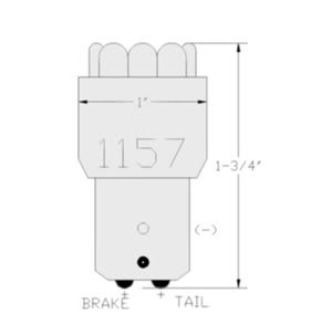
How do you make this so it can plug right into the car? By using the empty BA15 bases included in the parts list to make wires that will plug directly into the OEM tail lamp sockets. For each taillight, the FD uses one �single contact� plug (1156) for the turn signal and then two �dual contact� plugs (1157) for the brake lamps. The dual contact plugs activate one side of the wiring when you turn on the parking lights and then the other side of the socket for the brakes. So, for the turn signals, you�ll use a single contact plug that will have two wires coming out of it, one for a positive and one for a negative. For the brake lights, you�ll wire up two three wire plugs, with each having one negative wire soldered into the inside of the socket housing and then two positive wires, one for the parking lights and then the other positive to activate the brakes.
I fabricated up my own wires for this. I used 22-gauge wiring and soldered in the positives and then the one negative soldered into the inside of the socket. Here is what the results look like:
You end up with two three-wire plugs and one two-wire plug for each assembly. I used black RTV high-temp silicone to seal up the �cups� of the plugs and the wires.
Which side of the dual contact 1157 brake socket is used for the high-powered circuit mounted light and which is used for the parking lights?
Here is a pic that should help:
Rotate the 1157 bulb socket toward you so the lower of the two pegs on the outside of the housing is facing you. The higher peg will be away from you. Now look at the bottom of the socket. You�ll wire up the brake lights to the left side of the socket and the parking lights to the right. If you happen to get it backwards, then simply switch the wiring around.
For all bulbs, you�ll have only one negative wire for each assembly that is shared between the parking and the brake lights.
11-02-11, 10:45 PM
#12
Wiring the Amber Turn Signal Rings
If you wish to add in amber turn signal rings, you�ll need to wire up the amber ring to one of the two red parking light brake rings. I did this by drilling a hole through the OEM turn signal area into the brake light section:
I then threaded the wiring from the amber LED ring thru the turn signal section into the brake area and then soldered in this wiring into one of the two red parking LED ring wiring. Remember to silicone any holes that can let outside water into the housing. I used black RTV to silicone around the back side of the holes for the wires.
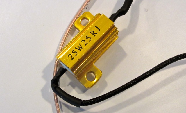
The final wiring step is to install a 25-watt �load resistor� into each turn signal assembly. This load resistor is used to ensure the turn signals don�t quick flash indicating a bulb outage. The FD gets fooled by LEDs as they consume so little power the FD thinks a bulb is out when it is not. A way to solve this is to wire in a load resistor, which cures the problem. Here is a link to how to wire in the load resistors:
http://www.superbrightleds.com/pdfs/...istor_info.pdf
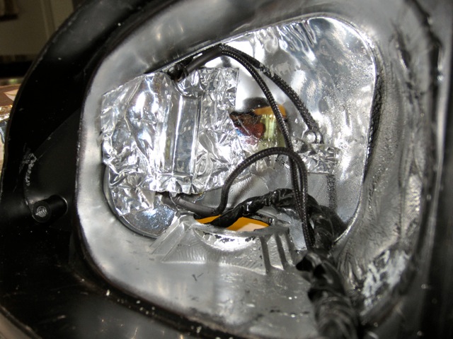
It�s so easy you can�t mess up. Note I used 25-watt units as they work and produce � the heat of the 50-watt units most use. They are also smaller which makes putting them in the turn signal areas much easier. Here is a pic of one installed into the inside reflector area of the OEM turn signal housing. I used metal tape for this. Works and keeps the resistor away from the other components.
You don�t have to use load resistors at all. Dale Clark has found a nifty way to modify the FD turn signal relay that does away with the use of the resistor:
https://www.rx7club.com/3rd-generation-specific-1993-2002-16/led-turn-signals-mod-your-flashers-right-way-943516/
Much better idea IMO. I then finished up the wiring by wrapping it all with electrical tape.
If you wish to add in amber turn signal rings, you�ll need to wire up the amber ring to one of the two red parking light brake rings. I did this by drilling a hole through the OEM turn signal area into the brake light section:
I then threaded the wiring from the amber LED ring thru the turn signal section into the brake area and then soldered in this wiring into one of the two red parking LED ring wiring. Remember to silicone any holes that can let outside water into the housing. I used black RTV to silicone around the back side of the holes for the wires.
The final wiring step is to install a 25-watt �load resistor� into each turn signal assembly. This load resistor is used to ensure the turn signals don�t quick flash indicating a bulb outage. The FD gets fooled by LEDs as they consume so little power the FD thinks a bulb is out when it is not. A way to solve this is to wire in a load resistor, which cures the problem. Here is a link to how to wire in the load resistors:
http://www.superbrightleds.com/pdfs/...istor_info.pdf
It�s so easy you can�t mess up. Note I used 25-watt units as they work and produce � the heat of the 50-watt units most use. They are also smaller which makes putting them in the turn signal areas much easier. Here is a pic of one installed into the inside reflector area of the OEM turn signal housing. I used metal tape for this. Works and keeps the resistor away from the other components.
You don�t have to use load resistors at all. Dale Clark has found a nifty way to modify the FD turn signal relay that does away with the use of the resistor:
https://www.rx7club.com/3rd-generation-specific-1993-2002-16/led-turn-signals-mod-your-flashers-right-way-943516/
Much better idea IMO. I then finished up the wiring by wrapping it all with electrical tape.
11-02-11, 10:46 PM
#13
Putting It All Together
At this point you�ll have three assemblies built for each tail lamp, two 80 mm units for the brake sections and one 75 mm unit for the turn lamp area. You�ll also have them wired up.
I first test fitted the units to ensure they would work.
Some shots of the test fits:
At this point you�ll have three assemblies built for each tail lamp, two 80 mm units for the brake sections and one 75 mm unit for the turn lamp area. You�ll also have them wired up.
I first test fitted the units to ensure they would work.
Some shots of the test fits:
11-02-11, 10:48 PM
#14
Your final step is to secure each unit over the corresponding 99 spec inside round ring plastic section. I did this by first positioning the units so they were centered over each 99 spec ring (exactly covering the plastic lens openings) and I then siliconed them down with RTV black high-temp adhesive (and then clear when I ran out of the black stuff ☺). Works well and can be removed later if needed. Here are pics of the assemblies:


Note I used a few metal shims on one left unit and turn lamp assembly to ensure the units did not move when I installed them back in the OEM housings. On the right side OEM turn signal unit I also used my Dremel to shave off a small section of the left side of the plastic lens edge to ensure the unit slid back in properly. The left taillight needed no such trimming, which can�t be seen anyway. It�s a tight fit but it works.
Check out the pics for wiring positioning and for where I located the LED drivers. Also insert the one 1156 socket and the two 1157 sockets through the holes in the back housings so you can easily plug in the newly modified assembly.
To reinstall, simply press back into position making sure to reinsert the tabs properly and to screw the sections back on. Then, reheat the glue on the clear plastic lens cover and the OEM back housing and press back together. Replace the screws and you are done. Plug back into your FD and enjoy!
11-03-11, 03:34 AM
#15
David, I finished my lights about 2 weeks ago and they turned out better than expected I copied the cones used on the brakes and was able to use 2 amber led rings in my turnsignals but it is tight in the housing the tri-stars are brighter and would be better for long distance visability (hazard flashers).
on the brake light cones I would recommend increasing the length of the metal for the cone a little to have enough material to overlap for the rivit and after mounting my tri-star leds to the heatsink I drilled a small hole in the heatsing to route the wire though. everything is easy to figure out once you are inside just time consuming. I have a few pics but none of them turned out well
anyone worried about heat from the high output led's I left my brakelights on in my car for 3 hrs straight while working on something else none of the led lights (Hayes-spec or Theorie -spec) ever got the housings warm but the third brakelight was so hot I couldn't hardly touch it.
11-03-11, 07:06 AM
#18
David, I finished my lights about 2 weeks ago and they turned out better than expected I copied the cones used on the brakes and was able to use 2 amber led rings in my turnsignals but it is tight in the housing the tri-stars are brighter and would be better for long distance visability (hazard flashers).
on the brake light cones I would recommend increasing the length of the metal for the cone a little to have enough material to overlap for the rivit and after mounting my tri-star leds to the heatsink I drilled a small hole in the heatsing to route the wire though. everything is easy to figure out once you are inside just time consuming. I have a few pics but none of them turned out well
anyone worried about heat from the high output led's I left my brakelights on in my car for 3 hrs straight while working on something else none of the led lights (Hayes-spec or Theorie -spec) ever got the housings warm but the third brakelight was so hot I couldn't hardly touch it.
on the brake light cones I would recommend increasing the length of the metal for the cone a little to have enough material to overlap for the rivit and after mounting my tri-star leds to the heatsink I drilled a small hole in the heatsing to route the wire though. everything is easy to figure out once you are inside just time consuming. I have a few pics but none of them turned out well
anyone worried about heat from the high output led's I left my brakelights on in my car for 3 hrs straight while working on something else none of the led lights (Hayes-spec or Theorie -spec) ever got the housings warm but the third brakelight was so hot I couldn't hardly touch it.
As for the metal for the cone, the template I posted should give you enough overlap material for riveting. In fax, you'll need to trim some of it off I suspect and well as the templates for the outer housings. The Theorie lights do not have any overlap and if you used this as a template, then that is what happened.
How about posting up some installed shots when you get a chance? Would love to see them.
What do you mean by the third brake light? The turn signal unit? If so, the heat is from the 50 watt load resistor. It gets insanely hot, especially with the length of time you left it on, which of course would not be a real life experience. This is why I opted to use the 25 watt load resistors. They use 1/2 the power and don't get nearly as hot. Of course, the flasher mod that Dale Clark has done eliminates this concern.
11-03-11, 09:53 AM
#20
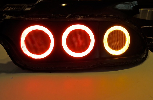
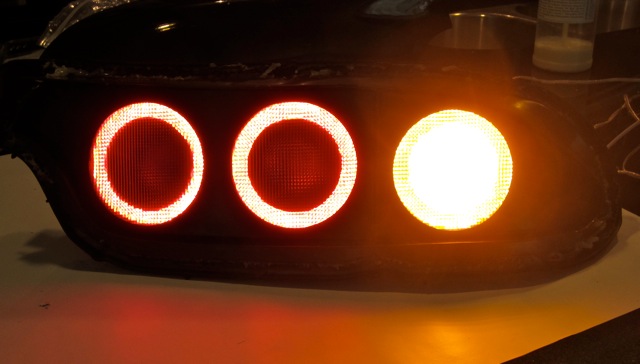
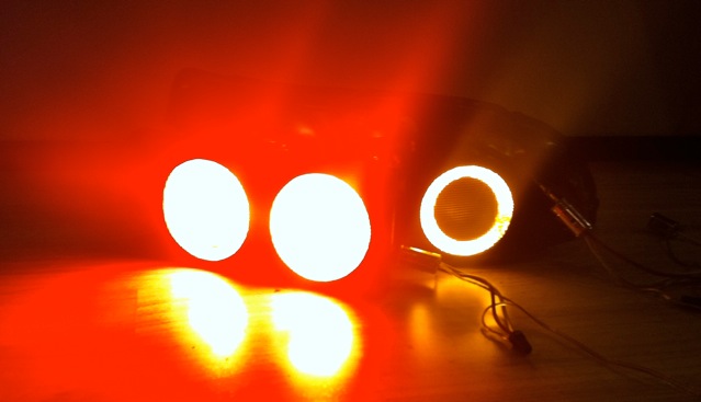
The pics show up for me. Interesting. The first post had three pics of the completed lights. Here they are:
Parking Lights
Turn Signal
Brake Lights
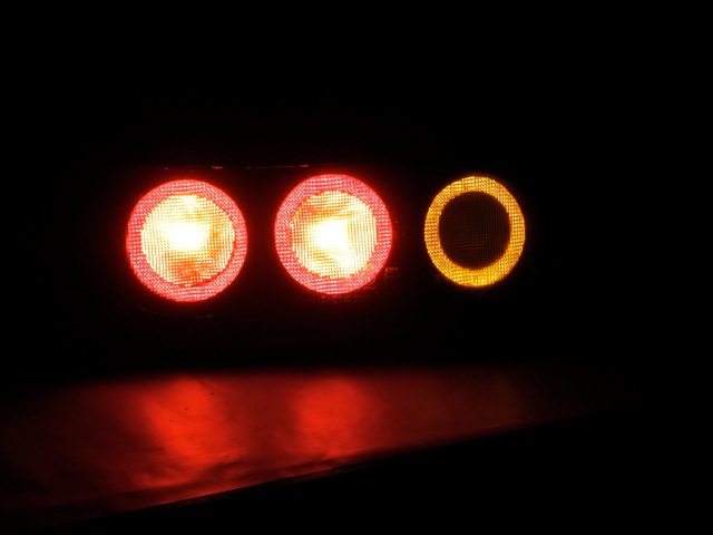
The camera washes out the colors of the red and amber rings when the turn signal or brake lights are on but in reality they stay like what is in the first pic.
Let me know if these are the pics you wanted or if you meant something else.
11-03-11, 11:52 AM
#22
I'd say it's a good weekend's worth of work or maybe up to three days. Not the quickest but not too bad if you are moderately good with a soldering iron and understand the basics of electrical work. A lot of time is wasted waiting on glue and adhesives to dry as you make the assemblies.
Most of the work for me in this project was spent on countless hours researching LEDs and what would work best for this application. I've got a bag full of other style LEDs that I'll sell cheap The coolest LED array I tested was a 7 LED circuit mounted one from luxeon.com. If you think the current brake lights are bright, that baby will bore a hole in your retina. I also have numerous hours involved in light output testing of the original Theorie units to determine the primary sources of light output degradation as well as the best methods to correct the issues.
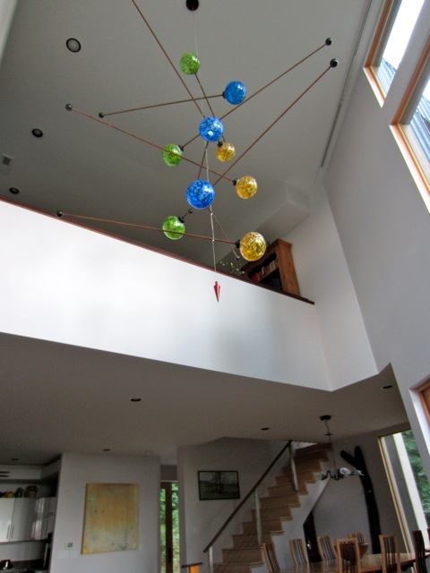
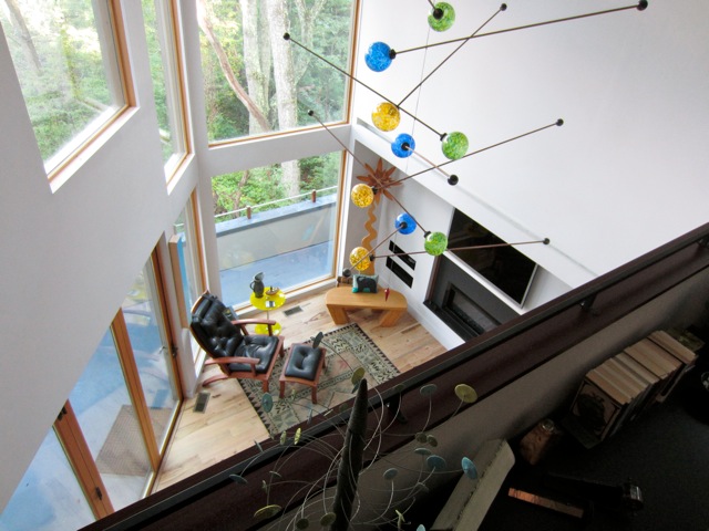
For whatever reason, I've been into LED technology for about 5 years. I've designed and fabricated some pretty cool stuff, including this LED chandelier for my home up in the mountains of NC:
But back to the taillight project. Timing-wise I'd say:
(4) hours cutting out the metal pieces and forming them into housing rings and reflectors;
(2) hours making the acrylic rings;
(2) hours fabricating the high-powered LED/heat sink/back plates units;
(1) hour making the 80-60 mm LED rings and rewiring them;
(2) hours putting together above pieces to form the 6 assemblies for the modification;
(4) hours doing all of the wiring including hooking up the LED drivers and the turn signal load resistors;
(2) hours gluing/affixing the units to the plastic lenses; and
(2) hours putting it all back together
That's 19 hours total which seems about right for doing it the first time. Once you'd done it once I'd say you could cut the time down to around 8 hours or so.
Most of the work for me in this project was spent on countless hours researching LEDs and what would work best for this application. I've got a bag full of other style LEDs that I'll sell cheap
The coolest LED array I tested was a 7 LED circuit mounted one from luxeon.com. If you think the current brake lights are bright, that baby will bore a hole in your retina. I also have numerous hours involved in light output testing of the original Theorie units to determine the primary sources of light output degradation as well as the best methods to correct the issues.For whatever reason, I've been into LED technology for about 5 years. I've designed and fabricated some pretty cool stuff, including this LED chandelier for my home up in the mountains of NC:
But back to the taillight project. Timing-wise I'd say:
(4) hours cutting out the metal pieces and forming them into housing rings and reflectors;
(2) hours making the acrylic rings;
(2) hours fabricating the high-powered LED/heat sink/back plates units;
(1) hour making the 80-60 mm LED rings and rewiring them;
(2) hours putting together above pieces to form the 6 assemblies for the modification;
(4) hours doing all of the wiring including hooking up the LED drivers and the turn signal load resistors;
(2) hours gluing/affixing the units to the plastic lenses; and
(2) hours putting it all back together
That's 19 hours total which seems about right for doing it the first time. Once you'd done it once I'd say you could cut the time down to around 8 hours or so.
Last edited by Narfle; 10-09-19 at 02:00 PM.
11-03-11, 03:02 PM
#23
David, I am very happ with the output now Thanks for the assistance in part sourcing/info.
I will try to have a buddy take a few nice ones soon.
The third brakelight I was talking about is the center one on the car I had a metal bar on the brake pedal to see what it looked like and was tinkering with something else and forgot to remove it untill I was locking up for the night and the brakelights were still on the led lamps/housings were not hot but the center with old incandecents was cookin' not something real world would see but good to know.

