Billion VFC Max
 02-16-06, 06:40 AM
#1
Crispy Beef
Thread Starter
Join Date: Oct 2004
Location: UK
Posts: 134
Likes: 0
Received 0 Likes
on
0 Posts
Billion VFC Max
I've got a Billion VFC Max gauge installed on my FD, was done before I had it when it was still in Japan. Problem I have is I want to check out some of the wiring but the manual is all in Japanese.
I've hunted around the web a bit and found the company's website plus several retailers and used Googles translation stuff which works well. The manuals are available in PDF but not in English, wondered if anybody has this manual in English or knows where else I could look?
Cheers.
I've hunted around the web a bit and found the company's website plus several retailers and used Googles translation stuff which works well. The manuals are available in PDF but not in English, wondered if anybody has this manual in English or knows where else I could look?
Cheers.
 02-16-06, 09:24 AM
#2
RX-7 Bad Ass
iTrader: (55)
I'm pretty sure that's Billion's fan controller. I have an HKS fan controller, which is somewhat similar.
If you can send me a link to one of the Japanese manuals, I might be able to decipher it - I've gotten pretty handy at it .
.
Dale
If you can send me a link to one of the Japanese manuals, I might be able to decipher it - I've gotten pretty handy at it
.Dale
02-16-06, 10:43 AM
#3
Crispy Beef
Thread Starter
Join Date: Oct 2004
Location: UK
Posts: 134
Likes: 0
Received 0 Likes
on
0 Posts
Originally Posted by DaleClark
I'm pretty sure that's Billion's fan controller. I have an HKS fan controller, which is somewhat similar.
If you can send me a link to one of the Japanese manuals, I might be able to decipher it - I've gotten pretty handy at it.
Dale
If you can send me a link to one of the Japanese manuals, I might be able to decipher it - I've gotten pretty handy at it
.Dale
02-17-06, 11:00 AM
#4
Crispy Beef
Thread Starter
Join Date: Oct 2004
Location: UK
Posts: 134
Likes: 0
Received 0 Likes
on
0 Posts
Here's the two relevant pages from the manual scanned in...am sure these are correct as they have grubby prints over them too. 
If anybody can let me know what the connections are then that would be great. I'm trying to rule out some bad wiring on this gauge from another problem I'm having with my FD:
https://www.rx7club.com/3rd-generation-specific-1993-2002-16/fuel-problems-508684/
If anybody can let me know what the connections are then that would be great. I'm trying to rule out some bad wiring on this gauge from another problem I'm having with my FD:
https://www.rx7club.com/3rd-generation-specific-1993-2002-16/fuel-problems-508684/
Last edited by Crispy Beef; 02-17-06 at 11:05 AM.
02-17-06, 11:17 AM
#5
RX-7 Bad Ass
iTrader: (55)
OK, I'm sorting this out a bit.
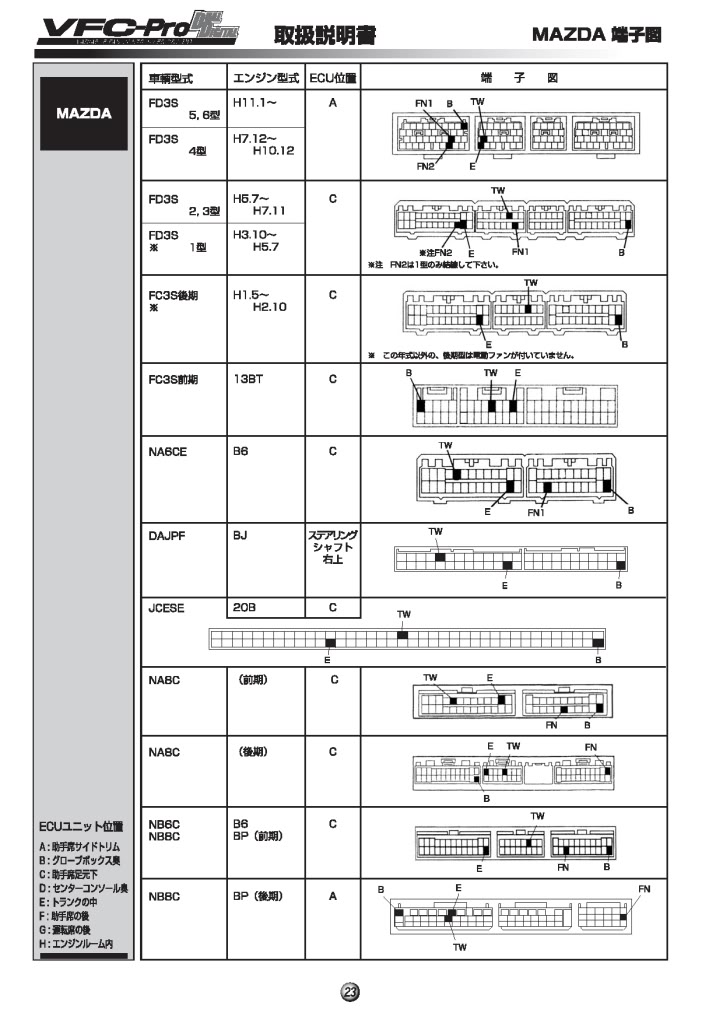
On the second page, that's the main one to look at. The one circled is I'm assuming the one they used - I'm guessing you have a '93-95 car.
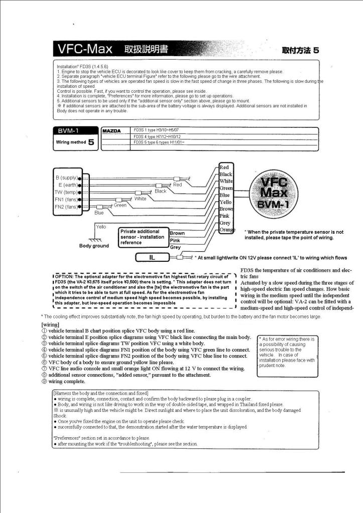
"B" is 12v switched - that's power for the gauge. "E" is earth, or ground, for the gauge. TW is the main temp sensor for the ECU - that's how the gauge can see what your coolant temp is, and figure out when to switch the fans on. FN1 and FN2 are the fan control outputs.
Tricky part is the fan outputs. FN1 is correct - that controls one of the fan relays. FN2, on my US shop manual, goes to the split air bypass valve. They have a note on that wire that I can't read. But, there is a nearby wire that you can use for the second fan speed - I'd have to look it up.
Can't tell much from the first page without figuring out what symbol is what wire color, and that's much harder without the gauge in front of me.
Hope that helps!
Dale
On the second page, that's the main one to look at. The one circled is I'm assuming the one they used - I'm guessing you have a '93-95 car.
"B" is 12v switched - that's power for the gauge. "E" is earth, or ground, for the gauge. TW is the main temp sensor for the ECU - that's how the gauge can see what your coolant temp is, and figure out when to switch the fans on. FN1 and FN2 are the fan control outputs.
Tricky part is the fan outputs. FN1 is correct - that controls one of the fan relays. FN2, on my US shop manual, goes to the split air bypass valve. They have a note on that wire that I can't read. But, there is a nearby wire that you can use for the second fan speed - I'd have to look it up.
Can't tell much from the first page without figuring out what symbol is what wire color, and that's much harder without the gauge in front of me
. Hope that helps!
Dale
02-18-06, 09:01 AM
#7
RX-7 Bad Ass
iTrader: (55)
Yep, that's the ECU. Passenger side kick panel.
Dale
Dale
Trending Topics
10-30-07, 06:29 AM
#8
Newbie

Join Date: Oct 2007
Location: New Zealand
Posts: 2
Likes: 0
Received 0 Likes
on
0 Posts
Hey,
Any of you guys ever seen this model of VFC by Billion. I can't for the life of me find an instruction manual. Ready to give up and take a hammer to it...
Need to know what each wire should go to, there are seven wires;
2 Black, 1 Red, 1 White, 1 Brown, 1 Green, 1 Yellow. I'm guessing blacks both go to earth, the red maybe constant 12v, yellow an acc 12v, (or the other way round), then... one goes to a water temp sensor, one to an oil temp sensor, one goes to a fan relay, and the other maybe fan speed?
Any help would be so greatly appreciated.
Cheers Guys,
Steve

[img=http://img3.freeimagehosting.net/uploads/de2df5a5f4.jpg]
Any of you guys ever seen this model of VFC by Billion. I can't for the life of me find an instruction manual. Ready to give up and take a hammer to it...
Need to know what each wire should go to, there are seven wires;
2 Black, 1 Red, 1 White, 1 Brown, 1 Green, 1 Yellow. I'm guessing blacks both go to earth, the red maybe constant 12v, yellow an acc 12v, (or the other way round), then... one goes to a water temp sensor, one to an oil temp sensor, one goes to a fan relay, and the other maybe fan speed?
Any help would be so greatly appreciated.
Cheers Guys,
Steve
[img=http://img3.freeimagehosting.net/uploads/de2df5a5f4.jpg]
08-17-08, 03:04 PM
#10
Junior Member
Join Date: Apr 2006
Location: UK
Posts: 29
Likes: 0
Received 0 Likes
on
0 Posts
English Translation For Billion VFC Max Fan Controller
Hope this helps anyone stuck without an english translation. I used online translation tools so its not translated perfectly but its not bad. Hope it helps.
Last edited by yogibear; 08-17-08 at 03:17 PM.
03-27-10, 08:13 PM
#11
Junior Member
Join Date: Apr 2006
Location: UK
Posts: 29
Likes: 0
Received 0 Likes
on
0 Posts
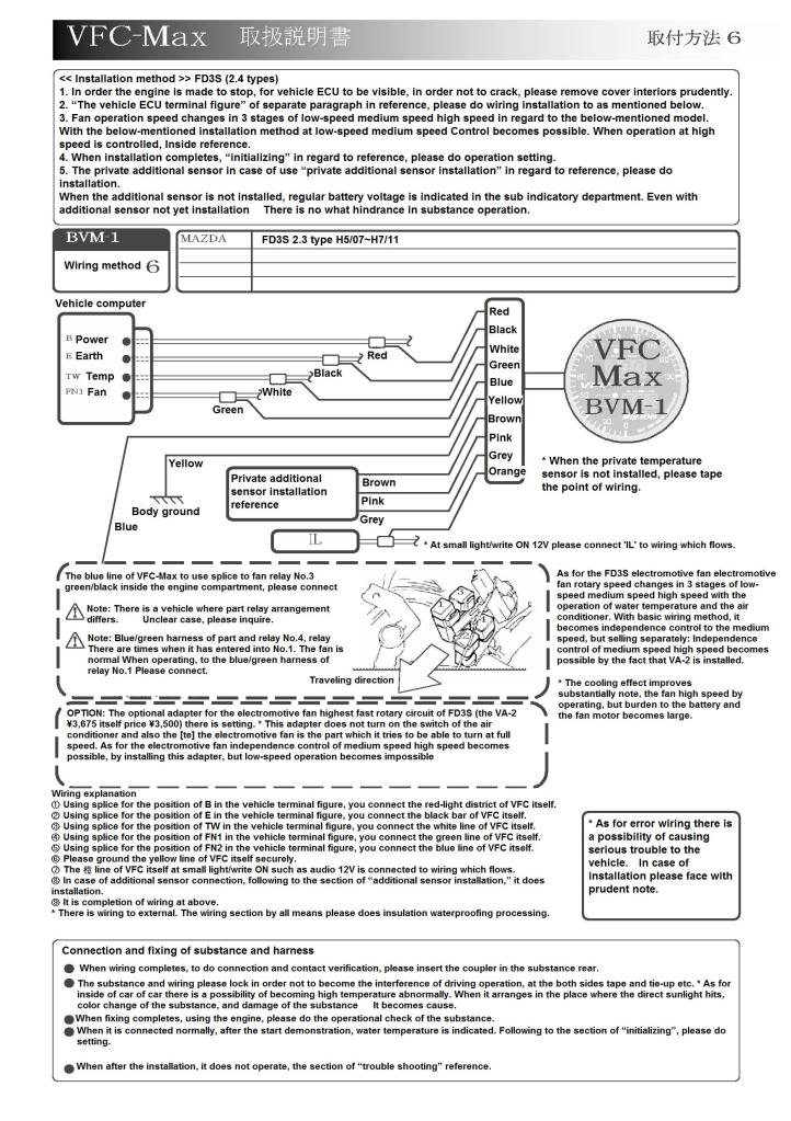
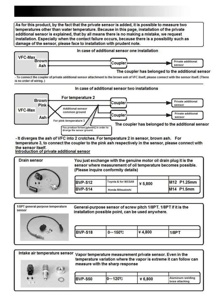
Update on my previos post , Ive included the two different versions for the fd3s, the connections sheet and the sensor listing. Hope it helps , mite mean ill be able to get mine working this easter.
Going to have a go at translating the instructions for setting up when I have a chance
Going to have a go at translating the instructions for setting up when I have a chance
03-28-10, 09:42 AM
#12
Junior Member
Join Date: Apr 2006
Location: UK
Posts: 29
Likes: 0
Received 0 Likes
on
0 Posts
Worked out the wire colours as well for plumbing into the ecu / relay
This is for my 1993 Jap Spec FD
Loom Colours
TW = Green / Orange water - temp feed
B = Black / White ignition - live
E = Brown / Black - Ground
FN1 = White / Blue
FN2 ECU = Black / Red
FN2 Relay = Blue / Green
Im unsure of two things , mainly how FN2 acts to turn on the fans, FN2 where it attaches to the relay as I was under the impression that to turn the fans on that way they would be earthed to the body to activate tham so Im going to do some testing and see what I can figure out. Secondly in the option where FN2 connects in to the ECU acording to my wiring diagram for the car the wire it plumbs into is for the Solanoid ( Split Air-Bypass ) which as far as I can figure out nothing to do with the cooling system.

Thread
Thread Starter
Forum
Replies
Last Post
frosty1993
General Rotary Tech Support
3
09-30-15 01:27 PM