When you click on links to various merchants on this site and make a purchase, this can result in this site earning a commission. Affiliate programs and affiliations include, but are not limited to, the eBay Partner Network.
Will the AEM smart coils work well with a stock ECM? I saw a post a couple years back that listed the dwell times for the OEM ECM coils (that looked to be little under the recommended dwell times), but I did not see feedback from any OEM ECU users. I would be interested in this setup, but I need something that will work with the OEM ECU, and with the PFC.
I like the idea of the stronger spark and opening up the area under the UIM a bit by removing the coil assembly, but I don�t want to have to switch back and forth between the stock coils and the AEM every couple of years when I have to undergo smog check.
If this system can work well with the OEM ECU then I would be a taker. If there is any firsthand experience on this I would appreciate hearing about it. Thanks!
Will the AEM smart coils work well with a stock ECM?
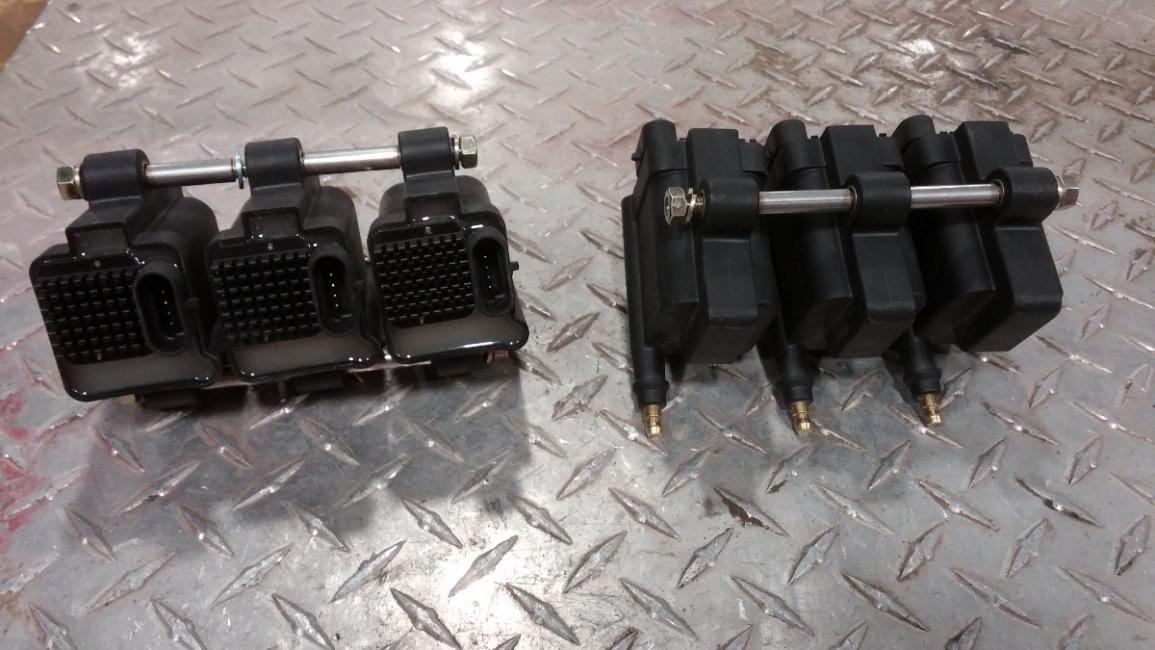
I don't think so. The stock ecm uses a separate igniter to run dumb coils. You would need their dumb coils. The IGN-1A smart coils have a built in igniter. The IGN do not.
It really makes no since doing something like this with the stock ecu and tune or pfc. Your better off going with a twin power. These smart coils are more for other aftermarket ecus that dont have built in igniters.
Even if the stock ignitor is removed as with the aftermarket ECU installations? I thought the critical factor was coil charge dwell time. But if it doesn't allow interchanging between the 2 ECMs then it won't work for me...
^ Thats why I posted info on the dumb coil. If your running something like a Haltech, you would be running its own wiring harness and not be reusing the fd one. Most fd owners run a PFC because its plug and play. You buy your coils based on the ecu's capabilites, not the other way around.
FYI....Dumb coils usually only have two lead inputs on the coil connector. Smart coils usually 4 or more. All stock Rx7's from the 1st gen to 3rd gen run dumb coils. The Rx8 runs smart coils.
I don't think so. The stock ecm uses a separate igniter to run dumb coils. You would need their dumb coils. The IGN-1A smart coils have a built in igniter. The IGN do not.
It really makes no since doing something like this with the stock ecu and tune or pfc. Your better off going with a twin power. These smart coils are more for other aftermarket ecus that dont have built in igniters.
These coils can be used on a stock fd, you would obviosly need to remove your coil and ignitor to replace with the ign1a. If you buy the SB garage kit there as complete as it comes. There harness by default run wasted spark just like the oem ecu or PFC.
It would be simpler to just buy a HKS amp but these coils can be ran on direct fire. Which in the long run will outperform the hks unit. So it really depends your intentions but the stock ecu cant configure the base dwell to 4.5 so you would sacrifice its true potential.
Thanks for the replies. This is what I was thinking, but my main question is how well the AEM coils will operate when driven with the stock ECU. I can't remember exactly, but somewhere in this tread a very helpful member posted stock coil dwell times and I think they were 2.8ms on the low end to 3.2? ms on the high end - not sure now exactly.
The question is, with these dwell values there is obviously a lot of spark energy being left on the table, but will the ignition performance still be better than the OEM coils, the same, or worse? If better (albeit not as good as it could be) , then that would help come smog check time by reducing HC emissions. But if the ignition performance was worse than the stock coils then that would not be good at all.
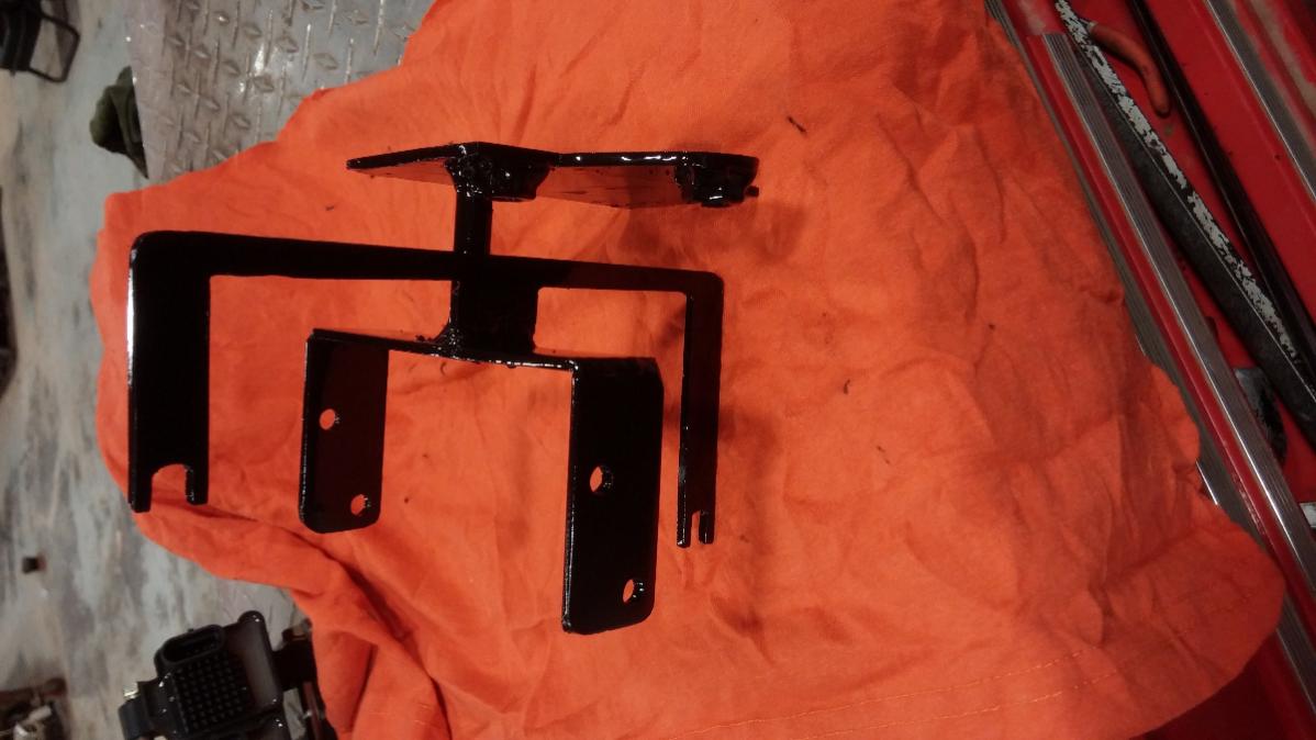
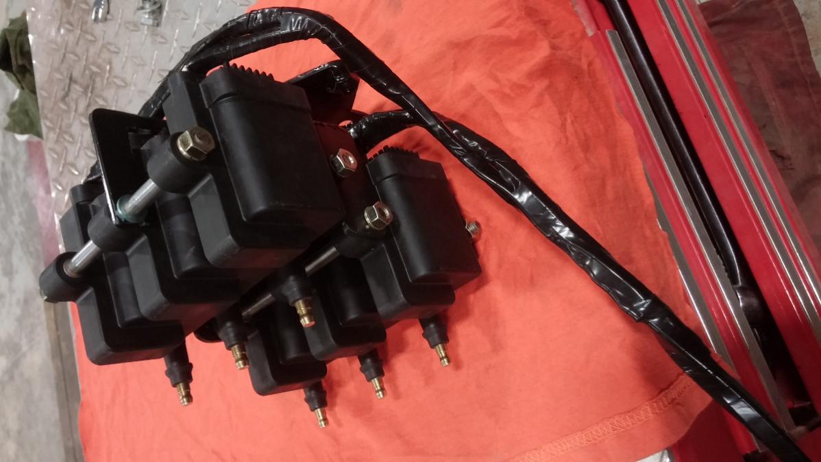
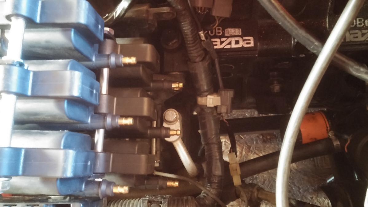
So I finally decided to buy me a set of AEM smart coils for my 13B-REW FD Rotary Engine for my STARXQUEST car, I wanted the ultimate ignition setup so I also made me my own custom Coil On Plug COP bracket, I don't need no stinking MSD spark plug cables.. Revs so much better, not the best pics I know.. I also re wired and re tuned my Haltech Sprint RE for the new COP Direct Fire setup.
The link below is to a vid of my RE reving up to a current 8100 rev limiter with AEM COP Direct Fire setup installed and engine recently rebuilt, ported and polished by me..
Thanks for the replies. This is what I was thinking, but my main question is how well the AEM coils will operate when driven with the stock ECU. I can't remember exactly, but somewhere in this tread a very helpful member posted stock coil dwell times and I think they were 2.8ms on the low end to 3.2? ms on the high end - not sure now exactly.
The question is, with these dwell values there is obviously a lot of spark energy being left on the table, but will the ignition performance still be better than the OEM coils, the same, or worse? If better (albeit not as good as it could be) , then that would help come smog check time by reducing HC emissions. But if the ignition performance was worse than the stock coils then that would not be good at all.
These coils CAN be run with the stock ECU, we've done it before with zero issues, and it cleaned up idle and some revving inconsistencies on the two cars we've done it on. We've got a number of customers that purchased the coils before upgrading to a power FC and mentioned similar improvements. These are just far better tech than the stock 20 year old coils, with a HKS twin power bandaid. Are you realizing the full potential of the coils in high boost applications? No, but if you're on a stock ECU you're not increasing boost and they're quite happy at stock dwell times. So, yes there is some potential benefit, you can yank the stock coils out from under your UIM to improve airflow, clean up your engine bay, and change nothing when upgrading to an aftermarket ECU. The harness comes jumpered with a purple wire to run waste spark unless specifically requested (required for stock ECU and PFC), and can be switched to direct fire in minutes for other aftermarket ECU's... simply cut the purple jumper, and extend the included blue wire out to your 4th signal wire. Done and done.
I bought a used harness with lms-efi.com on the harness but it does not have a relay attached, could this work without the relay or do i have to install one? i am hooking it up on a fd with a PFC.
I bought a used harness with lms-efi.com on the harness but it does not have a relay attached, could this work without the relay or do i have to install one? i am hooking it up on a fd with a PFC.
We use a 40A relay, you'll definitely want these on a relay, they have the capacity to draw a ton of power
Sorry to bring old thread back up but was wondering if someone wouldnt mind looking into my diagram for wiring up the IGN1A coils to the stock wiring and let me know if you see anything I need to change. I know this this has been covered several times, but just want to be sure. Thanks
Sorry to bring old thread back up but was wondering if someone wouldnt mind looking into my diagram for wiring up the IGN1A coils to the stock wiring and let me know if you see anything I need to change. I know this this has been covered several times, but just want to be sure. Thanks
I would at least separate the signal ground and attach it at the ground point at the back of the intake manifold. Not doing so would increase the risk of noise on the circuit. I also don't like grounding directly to the battery. I've not wired coils for waste spark, so I can't say that the way you have the trigger for the leading coils wired will work, or not.
I would at least separate the signal ground and attach it at the ground point at the back of the intake manifold. Not doing so would increase the risk of noise on the circuit. I also don't like grounding directly to the battery. I've not wired coils for waste spark, so I can't say that the way you have the trigger for the leading coils wired will work, or not.
Grounding directly to the battery is a requirement for POWER GROUND. This is very well documented, and known to cause issues if not followed.
As mentioned, you should not gang all grounds together...they are separate pins for a reason.
You have power ground, logic ground (sensor ground), secondary return ground. Many get away with ganging sensor and secondary ground without issue; they both have different requirements and should be segregated on paper, but in practice this typically seems to not be an issue.
If you search for any thread discussing this newer than 8 years ago, you will see this discussed.
Thanks guys for the time to look at my diagram. Please see the edited diagram with the grounds separated. For Pin B of the Coil Plugs, whats your opinion on where they should ground to? Battery, ECU, Chassis or Rotor Housing?
Actually this is how im going to do it. Just gonna have Pin B of the Coil Plugs go to a grounding point on the front housing. That way both rear and front housings are covered for either leading or trailing coil.
Actually this is how im going to do it. Just gonna have Pin B of the Coil Plugs go to a grounding point on the front housing. That way both rear and front housings are covered for either leading or trailing coil.
still incorrect...please search...
Your secondary return ground needs to connect to the rotor housing in which the coil is firing into. So you will have separate return ground for the front and rear rotors.
This loop area should be as short as practically possible, which is why most people ground to the knock sensor boss (if in used), as it is as close to the spark plug as you�re going to get.
I see, thanks for the help. Ill separate Pin C of the front and rear coils for front and rear housings.
Most what ive read not just this forum, Pin B needs to go to ECU Ground. So for my case, could I connect all coils Pin B to either Pins 4C or 4A or 4B of ECU Connector 4? Those are the grounds from that connector of the ECU looking at the factory diagram. But from what im understanding from you previous post, ganging Pin C and B still works alright even though technically your not supposed to?
still incorrect...please search...
Your secondary return ground needs to connect to the rotor housing in which the coil is firing into. So you will have separate return ground for the front and rear rotors.
This loop area should be as short as practically possible, which is why most people ground to the knock sensor boss (if in used), as it is as close to the spark plug as you�re going to get.
Technically per the AEM schematic you're correct, but in practice I can tell you that you can ground the "C" terminals on all your IGN1A coils to the same point on the keg, as long as it is a clean low resistance path to ground (i.e., heavy gauge wire, short run, and good clean connections). I've been running my FC that way for 3 years now, with the 4x coils "C" ground terminals feeding into a single, short 12AWG wire & lug bolted on one of the unused M8 threaded holes on the top of the center iron.
Notice in the AEM schematic, they refer to the grounding point for "C" as the cylinder head - I suspect they advise this because depending on the head gasket materials used on V type engines, there may be a bit more electrical resistance between the two cylinder heads where it could become a problem. This should not be an issue with a rotary, since the housings & plates are basically one solid low resistance electrical connection.
Technically per the properties of how the circuit works, it is the correct way . This is not just a DCR (resistance) issue. We are talking about a periodic signal with fast rise/fall times, this needs to be looked at more like a high frequency signal.
I�m not disputing your experience, but I can tell you from my own experience that can be a problem. You are the exception, not the rule. There are dozens of threads which document high rpm breakup on these coils, and 9/10 times the grounding strategy is the problem.
Chris Ludwig (probably the person with the most experience with these coils and the rotary bar none) has documented this as a problem. I have discussed this with Neil @ Pantera EFI, the designer of the coils (who is very familiar with the rotary and this application). Not to mention every professional harness that�s produced for these coils segregates the rotor grounds.
In regards to the instructions referencing a cylinder head, there are revised instructions which have been circulated by ECU manufacturers and other distributors/tuners referencing the rotor housings.
So even though you�ve had good luck with your method, let�s not advocate doing this incorrectly when he has the chance to do this correctly from the beginning with minimal effort.
For the OP, here�s just one thread where I�ve gone into a little more detail about what/why the different grounds are there for. I specifically talk about the sensor ground you�re inquiring about. You can actually see what I�m talking about where the old strategy from 8+ years ago has been revised given experience and what we know today.
Thanks DC5Daniel, I read through that thread and the Adaptronic article. I still dont fully understand the correct way to wire in the Sensor Ground. Seems the various stuff I read have their own argument to where it should be grounded. Could I just ground Logic/Sensor Ground of the coils to the same location of the grounds of the engine harness as its connected to the ECU?
If I end up grounding the Logic/Sensor Grounds to the same location as the Secondary Grounds, can I gang all four coils to either the rear or front housing or should I keep them separate like the Secondary Grounds?
Thanks DC5Daniel, I read through that thread and the Adaptronic article.
The Adaptronic article was more for that particular individual's self inflicted problem with a ground loop, though it does help explain the concept of loop area. I wanted you to see Chris Ludwig's advice, and how it has evolved over the years as communities got more experience with these coils. Again, he is the "expert" on these coils in these cars.
I still dont fully understand the correct way to wire in the Sensor Ground. Seems the various stuff I read have their own argument to where it should be grounded. Could I just ground Logic/Sensor Ground of the coils to the same location of the grounds of the engine harness as its connected to the ECU?. If I end up grounding the Logic/Sensor Grounds to the same location as the Secondary Grounds, can I gang all four coils to either the rear or front housing or should I keep them separate like the Secondary Grounds?
The generally accepted method, which all the professionally built harnesses for these cars choose to do, is to connect the logic/sensor ground to the same location you ground the secondary return (which is segregated by front and rear rotor). This is not "correct" as I explained in the linked thread, but the reason you can get away with this is because this ground is for the logic trigger of the coil, which has tolerance on the logic levels by design. The correct way would be to connect all four logic grounds to sensor ground on the vehicle harness (same ground for TPS and any other sensor with a dedicated ground back to the ECU), but virtually no one does this and it seems to be OK. As I explained in the other thread, the whole purpose of using sensor ground is so that the logic threshold does not unintentionally shift due to ground offsets caused by high currents in the power grounds. Any ground on the engine WILL experience an offset, as the Adaptronic article helps explain.
The secondary ground is more critical because it is the return path for the spark; this ground directly impacts the spark performance of the coil. The whole reason you have upgraded to these coils is the improve spark performance...which is why it makes no sense to increase the loop area and rely on the sandwiching of the irons and plates to make the return path of the entire keg "look" the same, which it's not when talking about a high energy pulse signal like spark.


 01-26-15, 12:52 PM


 . This is not just a DCR (resistance) issue. We are talking about a periodic signal with fast rise/fall times, this needs to be looked at more like a high frequency signal.