She Followed Me Home, Honest
 10-22-14, 10:15 AM
#1451
Moderator
iTrader: (3)
Join Date: Mar 2001
Location: https://www2.mazda.com/en/100th/
Posts: 30,798
Received 2,574 Likes
on
1,830 Posts
We fit the criteria.
I found the "spec" on the resistor packs (6 ohms resistance between the power in and power out pins) and will test it today.
Not sure if I hope that's it or not.
Apparently they are NLA from Nissan and used ones are kinda pricey (quick ebay search shows @$85).
There must be other cars that used similar systems and would have a usable option.
if we plug it into ohms law we see why, voltage/resistance = amps.
12v/5ohms = 2.4 amps
12v/12ohms = 1 amp
so basically if you wanted to replace them, you need ~6ohm resistors that can handle 16 volts or more, and shoot we'll say like 3 amps, as you want a lot of margin.
for checking yours, just test for resistance, and you will want to wiggle things around, it is possible to have the resistor be cracked and it sometimes works
 10-22-14, 11:55 AM
#1452
While screwing with the injectors/rail last week, I did a voltage test and saw battery voltage on all six connectors.
It wasn't till later that I wondered how that could be if there is a resistor pack in there, seems like it should be less, eh?
Off to check in a little while.
It wasn't till later that I wondered how that could be if there is a resistor pack in there, seems like it should be less, eh?
Off to check in a little while.
Back to the water-in-pipes analogy, if you have a pipe with a restriction in it at high pressure and a valve downstream is closed...
High Press ===:===X=== Low Press
then the part of the pipe beyond the restriction can fill up and will sit at the same high pressure. When you open the valve, the bit of pipe after the restriction starts emptying faster than it can fill through the restriction, so it's pressure drops.
 10-22-14, 01:16 PM
#1454
Yea, the DMM does, but when measuring voltage the internal resistance of the DMM is so high that it likely dwarfs whatever resistance is in the circuit you're measuring. This is one of the reasons that DMMs have ranges, so that a sufficiently high internal resistance can be chosen to not bleed off voltage while keeping it within measurable range.
In comparison, when the DMM is measuring amps, it must have a very low internal resistance so that it doesn't block the amps flowing through the circuit, thus why many meters have a different port to connect the + wire to when measuring current.
In comparison, when the DMM is measuring amps, it must have a very low internal resistance so that it doesn't block the amps flowing through the circuit, thus why many meters have a different port to connect the + wire to when measuring current.
10-22-14, 06:36 PM
#1456
Moderator
iTrader: (3)
Join Date: Mar 2001
Location: https://www2.mazda.com/en/100th/
Posts: 30,798
Received 2,574 Likes
on
1,830 Posts
ect is new.
injector resistor is good.
tps is probably ok too, the idle switch probably turns on the idle map, which might just use the rpm/coolant and not the afm. and or some emissions device(s).
ignition is ok, and timing is close enough?
are the injectors the correct ones?
are the injectors wired and placed correctly? i assume, that the ecu is batch fired, and it'll fire 3 at a time, and not all 6 at once, so having the right injector in the right place might matter
afm is a question. if it has a temp sensor, that should be easy to check, but the wiper is a bit tricky.
what else am i forgetting? what speed is it on? 33 or 45?
10-23-14, 09:01 AM
#1457
Well, a stunning bit of serendipity may land a Megasquirt in the Z.
Returning from a business trip, S. was talking to one of his engineers about the car and the guy wondered why he hadn't already swapped out ECUs. Turns out, this guy has a MS2, purchased for an abandoned project, and it could soon be ours.
Might know later today.
I eagerly await multiple new ways to fail.
10-23-14, 02:12 PM
#1459
MECP Certified Installer
10-23-14, 08:09 PM
#1460
Hmm, that's an interesting turn for this project! How does that work with CA's emissions standards tho? At least you'll actually know what the ECU is doing. Before he gets the MS, find out some things from the seller:
- Does it have the flyback circuits built for the injectors (to allow you to directly run the low-impedance injectors)?
- Does it have the high-current coil driver circuit built?
- Which tach input method is it configured for, Hall Effect (0-5V pulses) or variable reluctance?
- Are there any other circuits hooked up to the switchable inputs/outputs?
What type of crank angle sensor does the Z have? How many pulses per revolution, and any trigger on the cam (or at cam-speed)? I'm assuming the coil doesn't have any embedded logic, so it'll need the MS's high-current coil driving circuit. You could still use the FC AFM if you want (and it would probably help tuning along a bit if you can actually measure airflow), although this will probably require wiring up another input to get the MS to recognize it. I'd recommend including at least a narrowband (preferably wideband if you can spare the $200 or so) O2 sensor for some feedback if you're tuning it yourselves too.
10-24-14, 08:13 AM
#1461
All insightful and pertinent questions topless-person.
I have no answers to any of them and in fact, have zero experience with aftermarket EM systems, so I barely even understand the queries.
Probably a moot point- at least for now- as the guy can't find the Megasquirt and it's probably gone.
In a way, that's a good thing.
Maybe.
If we can't hook up and make the stock system run, what chance have we with a totally configurable setup?
Sigfrid and I are still at loggerheads over the probable cause, I say timing, he says fuel delivery.
I have gone over the instructions for engine assembly and keep coming back to one instruction in particular ("turn crank till #1 piston is at TDC on the compression stroke"), that makes no sense to me.
This direction comes BEFORE the head is installed, so cam position isn't a factor... what determines that the piston is TDC at compression based only on crank position?
10-24-14, 10:13 AM
#1462
All of those were questions to find out from the seller, so that you know whether it'll work for you or whether you'll need to build some of those circuits to control your engine. Either way, if he can't find it, then it doesn't matter.
Did you ever find out if the injectors were for a turbo, or are they correct for the engine?
Could the fuel pressure regulator be bad, and holding a higher fuel pressure causing the engine to be rich?
When you have the engine idling, have you tried pushing in or pulling on the AFM flapper door, not just connecting or disconnecting it? Maybe do this with the throttle propped open just enough to disengage the idle switch, so the ECU stops running the idle program (or mis-adjust the switch for the same effect)?
Is there a way of confirming that the AFM is the correct one for the ECU? Maybe one of them got swapped with a different model at some point before you acquired the car?
Have you tried testing the AFM? It looks like some pretty good instructions (but poor formatting) are here:
http://www.atlanticz.ca/zclub/techtips/afm/
It looks like there's a blob of glue that is supposed to hold the factory adjustment in place that can come apart or off, allowing the AFM to become pretty mis-adjusted, so this could certainly be a cause of many problems.
If its just the bottom end of the crank, the only thing that will determine TDC compression would be the timing gear that drives the distributor that you were just fiddling with, but it sounds like you've gotten that problem resolved (the hard, lonely way)
10-24-14, 03:44 PM
#1463
Moderator
iTrader: (3)
Join Date: Mar 2001
Location: https://www2.mazda.com/en/100th/
Posts: 30,798
Received 2,574 Likes
on
1,830 Posts
I have gone over the instructions for engine assembly and keep coming back to one instruction in particular ("turn crank till #1 piston is at TDC on the compression stroke"), that makes no sense to me.
This direction comes BEFORE the head is installed, so cam position isn't a factor... what determines that the piston is TDC at compression based only on crank position?
This direction comes BEFORE the head is installed, so cam position isn't a factor... what determines that the piston is TDC at compression based only on crank position?
as far as the crank itself, TDC is TDC, and the came decides if it is TDC on the compression, or TDC on the exhaust stroke.
the only gotcha i see with the datsun engine is that the distributor is timed from the crank, so THAT might set TDC compression, and then the cam would have to be in synch with the distributor and crank.
since the monty python references have stopped working, i will switch to sarcasm; its just a simple piston engine, you should just dissasemble the whole thing to check this, and pray to whatever god or gods you pray to, that you don't have a rotary, which is self orienting, except for the CAS, and that can go in 180 degrees off....
actually non sarcastically, how does the ECU know the engine is running, rpm wise? is it one wire, perhaps from the coil? or is it more that 1 wire?
ou might try this as well, http://www.atlanticz.ca/zclub/techti...ion/index.html
10-24-14, 04:44 PM
#1465
Moderator
iTrader: (3)
Join Date: Mar 2001
Location: https://www2.mazda.com/en/100th/
Posts: 30,798
Received 2,574 Likes
on
1,830 Posts
good. this means a few things, in no real order.
the ECU only sees rpm, so it has no way of knowing where the engine is in its cycle, so it cannot do sequential injection, as this would require a some reference to TDC #1 (the FC CAS referenced above is like this, there is an rpm signal, and a home signal)
i just looked at the wiring diagram, and i think that all the injector wires are the same color because they all fire at the same time.
10-24-14, 05:01 PM
#1466
Red Pill Dealer
iTrader: (10)

You can find TDC if you don't trust the pully marks/indicator. Check the indicator and pulley mark with a piston stop (through the spark plug hole). I made mine from an old plug, some bar stock, and a welder. Find compression stroke as a described above. This should get you to running and be able to put a light on it.
10-24-14, 05:08 PM
#1468
Red Pill Dealer
iTrader: (10)
Because that's the way they always did it! j/k. Though really, sometimes it's the answer.
10-24-14, 07:55 PM
#1469
Moderator
iTrader: (3)
Join Date: Mar 2001
Location: https://www2.mazda.com/en/100th/
Posts: 30,798
Received 2,574 Likes
on
1,830 Posts
well there are 6 different pins too, i'd guess 3 injector drivers. could be wrong btw, it might batch fire
10-25-14, 10:02 AM
#1472
Moderator
iTrader: (3)
Join Date: Mar 2001
Location: https://www2.mazda.com/en/100th/
Posts: 30,798
Received 2,574 Likes
on
1,830 Posts
10-25-14, 12:13 PM
#1473
usually there are separate wires to keep the current down since each wire is only handling 1 injector, and each injector driver is only handling 1 or 2 injectors. its a bit cheaper to have 3 or 6 low-ish (~1-2 amp) injector drivers and flyback current (to handle back-voltage from the impedance of the coils in each injector), than to have one high-current setup. Also, all the wires (including others in the harness) can be very similarly sized which makes routing and bending the harness easier, and the current rating for all the pins in the ecu connector can be the same. You also get a little bit more failure-protection if something starts rubbing thru the harness,
10-25-14, 08:59 PM
#1474
OK, thanks for the useful info folks.
She runs.
She sat idling for over 20 minutes, hot starts beautifully, revs fine.
Our timing is spot on...until it's not.
As we twinked around with the timing (adjusting the distributor) every once in a while it went ragged and then recovered. We couldn't reliably replicate the issue but it was certainly there.
When it ran right though, it was very, very good.
Hmm, we think...what could be going on here?
We pull the distributor and start messing with it- spins free, doesn't have real wobble, seems pretty good. Decide to pull the ignition module, two screws on the outside and the box comes off, it's connected to a reluctor ring...which came out in three pieces when unscrewed.
Pretty sure that ain't supposed to happen.
We have a new distributor ordered.
Also fine tuned the TPS...what a stupid, aggravating POS that thing is, but did manage to eliminate most of the tailpipe smoke.
We are now very close, I think the new dizzy will get us over the hump.
There is also a Plan B now. Hope we don't have to, but it's in place.
10-26-14, 06:37 AM
#1475
A few random shots:
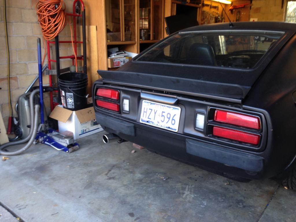
Pretty boring but actually one of my better finds.
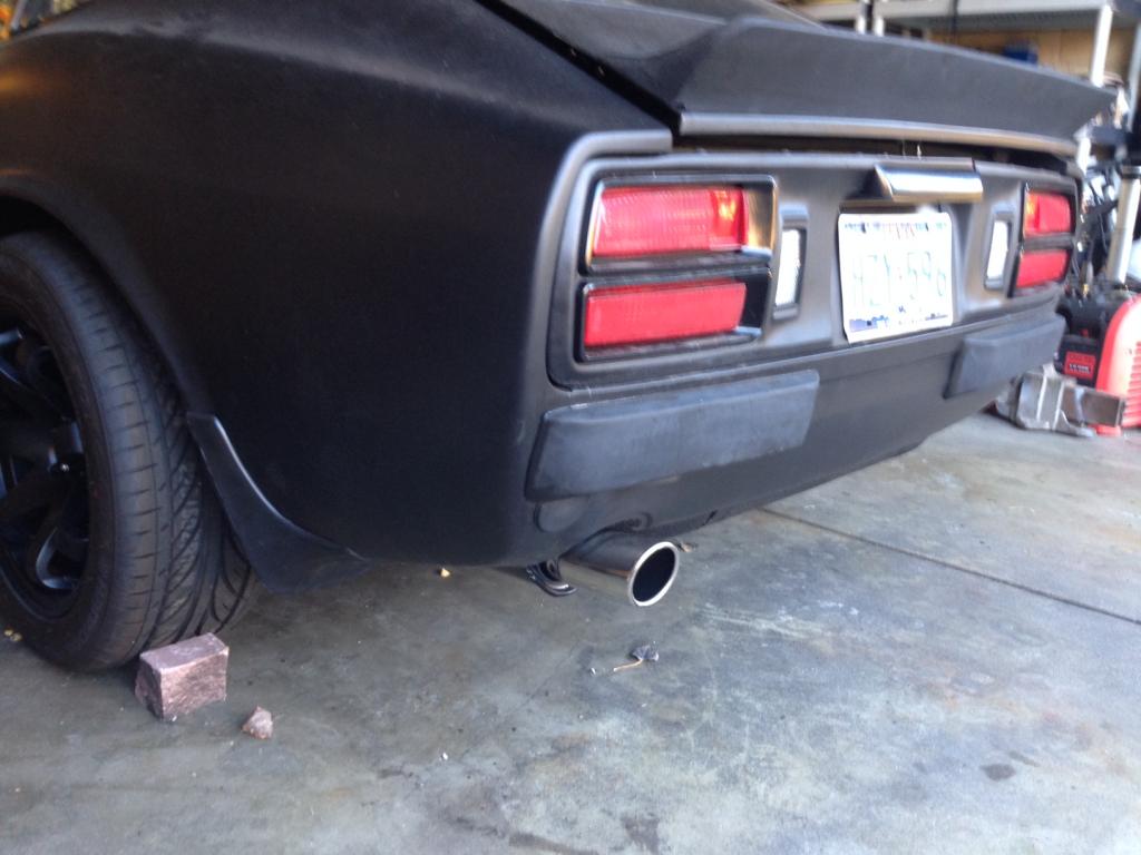
Recall that this car originally had giant crash bumpers, so the exhaust systems all come with giant long tips. Ours was even more hideous because it ballooned into a 4" fart can end, so it not only stuck out too far but was comically oversized.
I found this polished stainless tip on a clearance table at PepBoys ($7!) and made it fit.
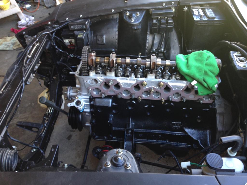
The engine last week:
And now:
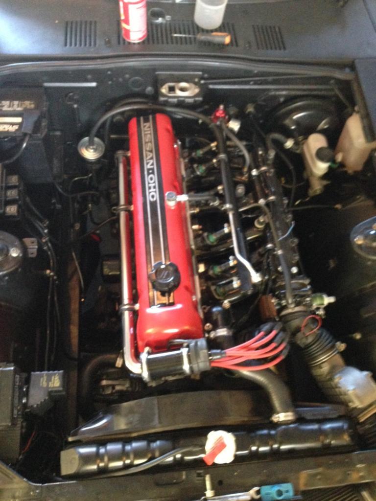
In the last pic, just to the right of the distributor cap, you see a (blurry) red circle.
This is actually the TPS connector and the red circle is a bit of wire used as a jumper.
This was during the "figure out the damn TPS" phase of the day and the jumper told the ECU that the throttle was closed.
Our TPS is actually two contact switches, one is closed with the throttle plate at rest and opens almost immediately.
The second switch makes contact with the plate about 70% open and tells the ECU you're headed to WOT.
Both switches were way off and our ECU never knew the throttle was closed and thought WOT was happening much sooner than it should...which is why she always ran so rich.
You're thinking, "What an idiot, why did he never check this before?" but I had.
Thing is, it's incredibly sensitive and just tightening the pivot bolts would throw it off.
Took me almost an hour to finally set it up.
Anyway, all I can do now is wait for Rock Auto.
Pretty boring but actually one of my better finds.
Recall that this car originally had giant crash bumpers, so the exhaust systems all come with giant long tips. Ours was even more hideous because it ballooned into a 4" fart can end, so it not only stuck out too far but was comically oversized.
I found this polished stainless tip on a clearance table at PepBoys ($7!) and made it fit.
The engine last week:
And now:
In the last pic, just to the right of the distributor cap, you see a (blurry) red circle.
This is actually the TPS connector and the red circle is a bit of wire used as a jumper.
This was during the "figure out the damn TPS" phase of the day and the jumper told the ECU that the throttle was closed.
Our TPS is actually two contact switches, one is closed with the throttle plate at rest and opens almost immediately.
The second switch makes contact with the plate about 70% open and tells the ECU you're headed to WOT.
Both switches were way off and our ECU never knew the throttle was closed and thought WOT was happening much sooner than it should...which is why she always ran so rich.
You're thinking, "What an idiot, why did he never check this before?" but I had.
Thing is, it's incredibly sensitive and just tightening the pivot bolts would throw it off.
Took me almost an hour to finally set it up.
Anyway, all I can do now is wait for Rock Auto.