HOW TO: Control an electric fan with a factory thermoswitch
 02-10-10, 11:49 AM
#1
HOW TO: Control an electric fan with a factory thermoswitch
For those of you doing an electric fan conversoin, you have multiple options for controlling the fan.
1. You can wire it to ignition power, but then the car will take a long time to warm up (if ever) and you will be draining the battery excessively.
2. You can wire it to a manual switch, but there's always the risk that you or anyone else driving the car may forget to turn it on.
3. You can use those crappy push-in radiator probe things, which hardly ever work.
4. You can use a Spal PWM fan controller, which will "throttle" the fan once configured correctly
5. You can use a thermoswitch, either a Mazda OEM one or a sensor off another car.
So there are multiple options for this. The automatic non turbo s4 cars came with a 195F/90C thermoswitch. The turbo cars came with a 207F/97C thermoswitch, the same temperature that the Rx-8's trigger their electric fans. Here is an OEM s4 turbo thermoswitch, located in the thermostat housing:
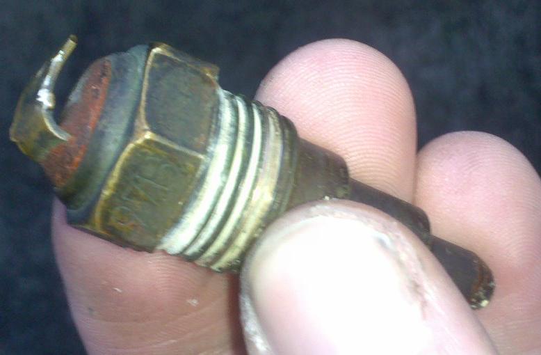
That is 3/8 NPT thread I believe. Here is the wiring diagram:
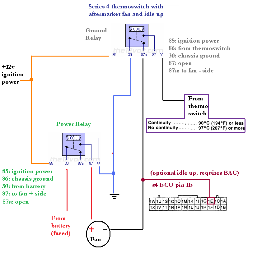
There are two relays. One controls fan power and one controls fan ground. With the key off, the fan will have ground but it will not have power. With the key on, the fan will have power but it will not have ground until the thermoswitch trigger temperature is reached. When the trigger temperature is reached, the thermoswitch will "remove" the signal to pin 86 of the ground relay. The chassis ground will be supplied to the fan through pin 87a, the normally closed pin. The fan will stay on until temps drop down below 195F/90C if you have a turbo thermoswitch. If you have an s4 nonturbo A/T thermoswitch, the ON and OFF temps will be lower.
It may look complicated, but that's about as simple as you're going to get using easily available relays. I tried to use splices and shared wires. The idle up function is achieved by sending a ground to s4 ECU pin 1E (same on turbo and non turbo) which will make the ECU think that the A/C is on. That will increase BAC valve duty cycle (more idle air) and advance the ignition timing from -5L -20T to 10L 10T, per the training manual.
1. You can wire it to ignition power, but then the car will take a long time to warm up (if ever) and you will be draining the battery excessively.
2. You can wire it to a manual switch, but there's always the risk that you or anyone else driving the car may forget to turn it on.
3. You can use those crappy push-in radiator probe things, which hardly ever work.
4. You can use a Spal PWM fan controller, which will "throttle" the fan once configured correctly
5. You can use a thermoswitch, either a Mazda OEM one or a sensor off another car.
So there are multiple options for this. The automatic non turbo s4 cars came with a 195F/90C thermoswitch. The turbo cars came with a 207F/97C thermoswitch, the same temperature that the Rx-8's trigger their electric fans. Here is an OEM s4 turbo thermoswitch, located in the thermostat housing:
That is 3/8 NPT thread I believe. Here is the wiring diagram:
There are two relays. One controls fan power and one controls fan ground. With the key off, the fan will have ground but it will not have power. With the key on, the fan will have power but it will not have ground until the thermoswitch trigger temperature is reached. When the trigger temperature is reached, the thermoswitch will "remove" the signal to pin 86 of the ground relay. The chassis ground will be supplied to the fan through pin 87a, the normally closed pin. The fan will stay on until temps drop down below 195F/90C if you have a turbo thermoswitch. If you have an s4 nonturbo A/T thermoswitch, the ON and OFF temps will be lower.
It may look complicated, but that's about as simple as you're going to get using easily available relays. I tried to use splices and shared wires. The idle up function is achieved by sending a ground to s4 ECU pin 1E (same on turbo and non turbo) which will make the ECU think that the A/C is on. That will increase BAC valve duty cycle (more idle air) and advance the ignition timing from -5L -20T to 10L 10T, per the training manual.
Last edited by arghx; 02-10-10 at 11:55 AM.
 02-10-10, 11:56 AM
#2
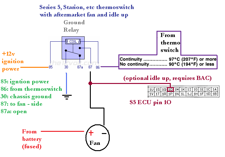
The s5 and most other thermoswitches are more straightforward, because they switch a ground at the trigger temperature instead of removing a ground at the trigger temperature. Here is a diagram for using an OEM s5 thermoswitch (all of which come on at 97C/207F) or most other thermoswitches:
02-10-10, 12:07 PM
#3
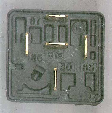
If you're only using one thermoswitch- and by extension, a one speed fan- you only need one relay, not two.
The coil side remains the same- +12v (switched) to pin 85, pin 86 to the switch (the optional idle up can also originate from pin 86).
Pin 30 gets fused +12v (matters not if this is switched) and pin 87 goes to the fan positive terminal.
Fan negative to any convenient ground.
The coil side remains the same- +12v (switched) to pin 85, pin 86 to the switch (the optional idle up can also originate from pin 86).
Pin 30 gets fused +12v (matters not if this is switched) and pin 87 goes to the fan positive terminal.
Fan negative to any convenient ground.
02-10-10, 12:15 PM
#4
If you're only using one thermoswitch- and by extension, a one speed fan- you only need one relay, not two.
The coil side remains the same- +12v (switched) to pin 85, pin 86 to the switch (the optional idle up can also originate from pin 86).
Pin 30 gets fused +12v (matters not if this is switched) and pin 87 goes to the fan positive terminal.
Fan negative to any convenient ground.
The coil side remains the same- +12v (switched) to pin 85, pin 86 to the switch (the optional idle up can also originate from pin 86).
Pin 30 gets fused +12v (matters not if this is switched) and pin 87 goes to the fan positive terminal.
Fan negative to any convenient ground.
Two relays are used in the s4 thermoswitch wiring diagram so that the fan is never on without the key in the "run" position and water temperatures at the trigger point. If you want to run the fans for a fixed time after the car shuts off, you will have to wire up an FD cooling fan control module. The FD cooling fan control module in conjunction with an s5 style thermoswitch (or an s4 thermoswitch with a relay to conver the signal) will run the fans for 10 minutes after the car shuts down. That's only if the fans were already running before the engine is turned off.
02-10-10, 12:32 PM
#6
and you should also note that you SHOULD use a high amp relay, a little dinky 15-20amp on a large e-fan will eventually melt down and cause more issue than anything else. you should also note to wire up a manual switch as a backup in case my original point occurs. wiring 2 relays in parallel is better than running a ground and ignition side(s5 and starion cases), in case one fails you at least have a backup working to get you where you are going.
the S4 switch is not ideal for the main points noted in this thread because it is a constantly closed(grounded) until open switch, which would either need two 40A relays or 4 20A relays wired up parallel. if you think a 20A relay(most commonly found in parts stores) is going to hold up, think twice.
good writeup but i still hate the *** backwards S4 switches.
Trending Topics
02-10-10, 06:47 PM
#8
On an s5 or other thermoswitch, this is true. See post #2. On a factory S4 thermoswitch that will result in the fan staying ON until the trigger temperature, at which point it will turn off. The s4 thermoswitch is unusual. Instead of having an open and then switching a ground at the trigger temperature, it always provides a ground until the trigger temperature is reached.
If you go to NAPA and look in their books there are literally dozens of thermoswitches that can be used on our cars- they have the proper thread and you can choose from a variety of trigger points.
And they're cheap (typically under $20), so it makes sense to me to grab a new, non-backwards switch instead of the extra relay/wiring for the stocker.
02-10-10, 10:15 PM
#11
Rotary Enthusiast
iTrader: (1)
Join Date: Mar 2007
Location: sc
Posts: 817
Likes: 0
Received 0 Likes
on
0 Posts
Thanks a lot. I was about to order a gsxr fan switch....but if i can save a few bucks im all for it. also lmao off at hitler bama....=1 for archive...one last question...on my s5 turbo...there was like a 10 inch efan...guessing that was for the ac?
02-10-10, 11:25 PM
#12
This would seem to be the perfect reason not to use the S4 switch then...this whole monkey cluster wiring setup just to accommodate a backwards switch.
If you go to NAPA and look in their books there are literally dozens of thermoswitches that can be used on our cars- they have the proper thread and you can choose from a variety of trigger points.
And they're cheap (typically under $20), so it makes sense to me to grab a new, non-backwards switch instead of the extra relay/wiring for the stocker.
02-10-10, 11:49 PM
#13
you really don't even have to use his S4 diagram anyways. you wire up the fan to constant power and the relay to a chassis ground and have the fan switch run constantly. the whole additional relay is unneeded. in all honesty it is better to have it operational even with the ignition off anyways because the car can overheat while heatsoaking.
02-10-10, 11:53 PM
#14
There is always a risk of unacceptable battery drain from this during hot weather, especially if you have a powerful fan and the engine experiences major heatsoak. That's why the FD OEM fan control module only allows the fans to run for 10 minutes after the car is shut off. I personally am not comfortable doing what you suggest on my own car, but to each his own.
my fan runs for 3 minutes at most when i shut it down, im sure it may for a little longer on really hot days but the reality is that if you have a decent battery(which you should) then it should take 30 minutes for even a HUGE fan to kill your battery.
but to each his own.
02-11-10, 12:09 AM
#17
mattg prob nt coming back
iTrader: (3)
Join Date: Feb 2005
Location: OrangePark FL
Posts: 1,933
Likes: 0
Received 0 Likes
on
0 Posts
i would like to do this with my taurus fan on my s4 t2 but i cant make heads or tails of the wiring diagram. im wiring diagram retarded lol. is there a way you could post pics of what needs to be spliced and the wires used. thanks
02-11-10, 12:33 AM
#19
Download the factory wiring diagrams and look through the opening section. It explains the basic symbols used in a wiring diagram. The numbers in my diagram refer to specific numbered pins on a 5 pin relay. If I made the writeup or wiring diagram too specific then I'd get a chorus of people saying "Why did you put that wire there? Why don't you just do it this way?"
The following users liked this post:
Mlammert (01-27-18)
 02-17-10, 10:19 AM
#23
It is definitely viable to do so. you'd just have to tap it off the fuse box or something. I thought about making a diagram like that up there ^, but I just didn't want somebody trying to power the fan off some TPS wire or something rediculous like that. You never know what can happen with people and electrical stuff. You give a simple diagram that requires more wiring knowledge and people do dumb **** and start complaining about problems. You make a more complex but also more idiot proof diagram and people say it's too complicated. Oh well.
oh btw... I said the s4 water temp sensor (and I think s5) is 3/8 NPT. That's not true. It's a similar diameter but the thread has to be something weird. It's a much coarser thread than that. The only thing I've found that screws in there is a freeze plug off an old Mazda B2000 motor.
oh btw... I said the s4 water temp sensor (and I think s5) is 3/8 NPT. That's not true. It's a similar diameter but the thread has to be something weird. It's a much coarser thread than that. The only thing I've found that screws in there is a freeze plug off an old Mazda B2000 motor.
02-17-10, 12:34 PM
#24
F**K THE SYSTEM!!
I use one o those push in probes with fuse and relay w/ adjustable temp.
NO splicing just wired to the battery. It was hard setting the thing to its proper temp but i havent had any problems yet.
But i like the set up you guys are using. I might switch to that style soon. with s5 switch=)
NO splicing just wired to the battery. It was hard setting the thing to its proper temp but i havent had any problems yet.
But i like the set up you guys are using. I might switch to that style soon. with s5 switch=)