When you click on links to various merchants on this site and make a purchase, this can result in this site earning a commission. Affiliate programs and affiliations include, but are not limited to, the eBay Partner Network.
Full Function Engineering trigger wheel with power steering!
So full function engineering sells an awesome 32-1 trigger wheel to replace the sloppy stock CAS for aftermarket ECUs. The problem is it's not compatible with power steering or AC. My front tires being 315 wide hoosier DOT slicks... I'm not getting rid of my power steering so here is a quick how-to on how to keep it.
First step, adding the power steering pulley to the main pulley:
I bolted the trigger wheel to the power steering pulley:
scried around where I had to cut:
scribe marks:
dremmeled holes into the pulley, the silver bracket is only about 3.35mm thick, so you don't have to take a lot of metal off. that being said, the pulley was a lot thicker than I thought it would be, so it took some time:
dremmeled the ring thing too. after my first pass I accidentally test fit it backwards and not surprisingly it didn't fit at all so I took way more material off than I needed too on the second pass which sucked.
done!, so now the p/s pulley is spaced out ~6.35mm from the bracket that holds the wheel. time to space out the other 2 pulleys.
first, the idler pulley:
I added 3x2mm washers, in reality, they probably should be nice big fender washers, I'll probably replace them when I can get some.
6mm spacing is close enough to 6.35mm for me.
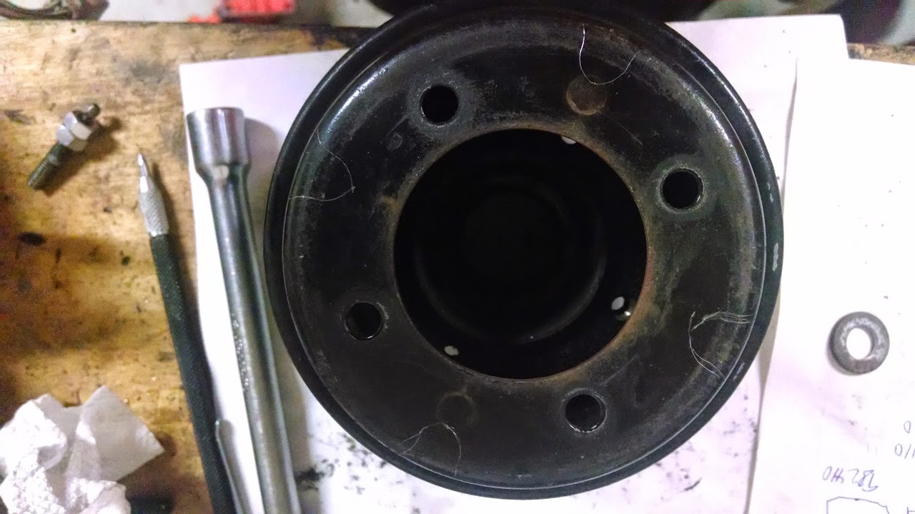
lastly the power steering pump pulley:
This ended up being easier than expected. I took the 3x10mm bolts that hold the pulley to it's boss. I measure the differences and it's 5.5mm deeper if you flip it over. (13.25mm vs 7.75mm) so that's all I did.
flipped pulley:
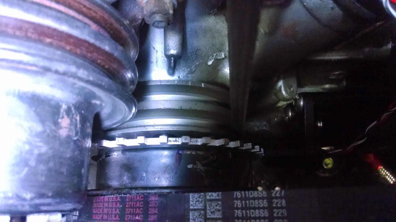
and now it's mounted:
looking at it mounted in those pictures... I definitely need larger washers on the idler pulley...
next step is to mount my hall sensor bracket... it uses the same studs as my re-located power steering bracket, but it doesn't look like it'll be very difficult. I'll update this thread when I complete that.
Snap. Sold my FFE because I have power steering and A/C. took one look at the AC and sold the FFE. Maybe I should have tried. Wonder if the adaptronic will run it. I also didn't think the bolts were long enough.
Clever idea eage8. When is part 2 - 'Mounting the trigger wheel sensor'? Also can you take a pic of the stock timing marks showing the clocking location to the FFE trigger teeth. Keep it up.
I aquired a stainless steel "jumbo washer" to use for the idler. 2" diameter x 0.25" thick (6.35mm) Mcmaster part #92303A106. Just had to drill the hole out from 13/32" to 27/64" and it was good to go. (the idler bolt has an odd sized large shoulder on it, about 10.7mm thick)
THIS ONLY APPLIES IF YOU'VE RELOCATED YOUR POWER STEERING
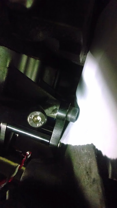
This was pretty easy. Here is what I was dealing with (sorry for the bad picture):
it's held on by 2 studs, one of which is spaced out with 13.5mms of washers to line up with the rear stud (and is the one we need to use.)
The FFE bracket is 10mm thick (actually ~9.8mm).
I took all the washer off and measured 3.5mm of washers to use again (1x 2mm washer, 1x 1.5mm washer, I was being OCD because I knew the spacing I had before worked... as long as the pullies line up you're good)
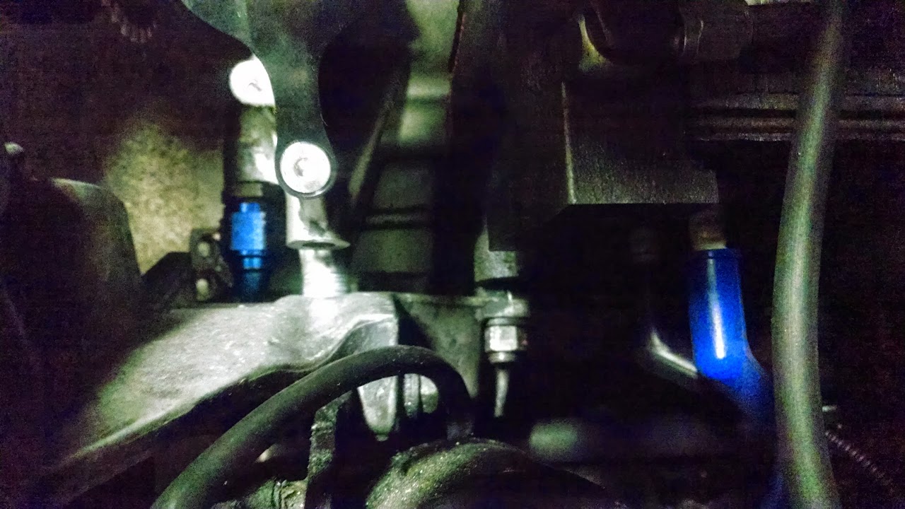
it was then as simple as slipping the sensor bracket over the existing stud that I was using and then bolting it on with the top provided bolt (I had already removed the stud to get the power steering relocated). you slip the 3.5mms of washers onto the back side of the bracket and bolt the P/S bracket back on.
easy peezy.
(and yes, there is clearance between the bracket and that bolt, I checked with a peice of paper )
Yeah, the sensor bracket is snug, but looks like you got it to fit OK. Since your trigger wheel is in the design axial location, it's probably well centered vs the sensor tip.
Thanx for the pic of the timing marks. Mostly interested if the FFE trigger wheel has a unique clocking position to the mounting ring, or if it can be rotated in 90 degree increments.
No,it can't be clocked any other way than that stock 4 bolt offset.The mount was designed like the stock pulley so it only goes on one way.
Well,the ONLY other way you could get it to go 'way out of whack' is to undo the little set screws on the mount and rotate it that way.(that way you "could" get it to go at 90 degree increments.)
..and those little screws are Really set ON there..lol..(trust me!)
Last edited by misterstyx69; 06-05-14 at 12:08 AM.
Yeah, the sensor bracket is snug, but looks like you got it to fit OK. Since your trigger wheel is in the design axial location, it's probably well centered vs the sensor tip.
Thanx for the pic of the timing marks. Mostly interested if the FFE trigger wheel has a unique clocking position to the mounting ring, or if it can be rotated in 90 degree increments.
ahh, so as styx said, yes it does have a single set location on a stock pulley, because one of the bolt holes is slightly offset. this is so the timing mark on the pulley stays in the right place if you remove and reinstall the main pulley on the hub.
it has a 2nd set of holes for 74-85 rx7s which as far as I can tell are the same, but not offset. so using those holes, you can rotate it 90* at a time if you'd like.
it has a 2nd set of holes for 74-85 rx7s which as far as I can tell are the same, but not offset. so using those holes, you can rotate it 90* at a time if you'd like.
a little pulley history.
the pulleys start life with a symmetrical 4 bolt pattern. early on they whole thing was riveted together. then later in the 70's, the rivet stays, but the pulleys aren't attached, the rivet fits in a hole in the pulley though, so putting it together wrong, is not really possible. then the Rx7 came out. it has the symmetrical pattern, but no rivets or other marks, so you can put the pulleys together 4 different ways, and obviously this makes finding TDC a bugger if you didn't mark anything before you started.
so for the FC they offset a bolt, and then that mostly fixes the problem (ive seen people drill out the bolt to put the pulley on wrong).
then the FD and Rx8 use the same pattern, but add locating pins
off topic slightly, but are you still using the factory speed sensing power steering setup eage8? Or have you swapped something else in?
Still using the stock speed sensitive power steering, it's fine. I don't really have any issues with it. It handles the 315/30/18 slicks on 18x12s up front without overheating which is more than I can say about a lot of cars...
Eventually I'll probably replace the lines with AN lines or something (because mine leak a bit), but haven't gotten around to figuring that out yet.
Awesome. I am still fighting with mine a bit from the PO removing the engine from the car. It seems a tad "off" but I have a minutia leak at the rack from the pressure side that I believe to be the culprit. I love it otherwise as well.
I'll be using this writeup and links inside in the future for sure!
Has anyone used a ffe trigger wheel with the stock a/c -pwr steering bracket or comment if it can be done?...would like to keep a/c and power steering.
Has anyone used a ffe trigger wheel with the stock a/c -pwr steering bracket or comment if it can be done?...would like to keep a/c and power steering.
It is possible, but you'll need the help of a machinist to modify the factory PS/AC bracket, a spare water pump/alternator pulley and some miscellaneous hardware to pull it off. Here's a picture of the end result, I've got fully functional PS & AC on my S5T2, using the FFE Hall effect trigger kit with an AEM Infinity ECU
Step #1 is to modify the factory bracket to fit precisely over the FFE trigger kit bracket, so that when it's all assembled, the trigger bracket is sandwiched under the PS/AC bracket and is tightly bolted up to the engine using all the stock studs & nuts. The modification to the PS/AC bracket involves milling the precise amount of material from the engine side of the bracket around the 2 stud hole pads (where FFE bracket goes) & surrounding area so it can fit over the FFE bracket without being misaligned or loose.
Step #2 is getting the PS & AC pulleys to align, which was the tricky part. First thing to do is replace the 4x M6 bolts fastening the pulley stack and replace them with M6 studs. The pulley stack goes back together on the E-shaft hub as follows: (1) Factory WP/ALT pulley, (2) FFE trigger wheel, (3) Now you'll need 4x aluminum spacers, IIRC, the spacer thickness that worked to get the belts aligned just right was 3/16", (4) Take a spare WP/ALT pulley, flip it around 180* and try to mount it - it won't slip over the 4 studs because one of the holes is offset, so that hole will need to be elongated slightly to fit over the four studs; elongate that one hole a bit and bolt it up with the M6 nuts.
End result works well; due to the differences in pulley diameter relative to the stock AC hub pulley, you'll be under-driving the AC a bit. My AC seems to be happy with that though, and it cools well enough. The PS pulley is also slightly under-driven for the same reason, but the difference there is negligible.
thanks for the reply...that is a very slick solution and super helpful.Pete_89T2
One way I was thinking of attempting this was to use a cosmo RE 5 rib wp/alt crank pulley and wp pulley I was saving ....the cosmo pulley is thinner then the double v-belt stock pulley...I found a 6-inch diameter 36-1 wheel that would work and not interfere with the wp pulley...would weld 4 small tabs on the cosmo 5rib outer diameter to either rivet or bolt the 36-1 wheel to ...the tricky part here is that the pulley tabs need to be machined true and the bolt hole circumference marked as well as marking the 36-1 wheel for the corresponding hole dia. on the lath so the toothed wheel runs true when bolted...FFE bolts the wheel to the crank adding distance...this allows the stock ps/ac v belt to be bolted spaced at the correct distance.
the cosmo 3 rib pulley needs to knocked off also ...for the sensor ..was going to make an arrangement similar to what FFE does but use a threaded hall sensor instead and only have to dick with getting the offset dimension correct and using the threaded version to set the gap right...wasn't sure about the bracket but can have that machined also now that you clarified.
I'm conflicted now...I like your solution
Awesome! I was going to attempt exactly what you did, Pete, as soon as my engine is back together, so glad it works! Cool idea about filing the spare pulley around, BTW. That was the last part I hadn't figured out.
Awesome! I was going to attempt exactly what you did, Pete, as soon as my engine is back together, so glad it works! Cool idea about filing the spare pulley around, BTW. That was the last part I hadn't figured out.
^I can't take credit for the flipped spare ALT/WP pulley idea, that was Brian's (TitaniumTT) genius idea, who helped with the build. We played around with a bunch of other schemes to get the AC & PS pulleys aligned, but nothing else worked nearly as well.
I felt like my alternator wasn't putting out enough juice at lower RPMs / idle. I have an electric water pump, 2 walbro 400s, 4 ign1a coils, and 2 big spal fans, so my electricity needs aren't negligible...
after talking to DC Power I realized my pully ratios weren't really ideal. which confirmed my suspicion. (Thanks DC power for pointing out my problem instead of just selling me an alternator)
old setup:
mystery FD alternator conversion pulley adapter originally sourced from silver rotor?
racingbeat main pulley
pulley ratio: 1.46:1
I liked the timing marks on the racing beat pulley and the fact that it's aluminum... and larger aftermarket pulleys are hard to come by, so this is what I came up with:
 06-02-14, 10:26 PM


 )
)