A/C Compressor Safety
 05-21-10, 12:07 PM
#1
A/C Compressor Safety
I took out my stock ECU and installed a haltech. Right now I have no controls for my A/C and I want to build my own ECU to control it. I am going to make my own ECU for the learning experience, and also so I can control the A/C by some haltech outputs as well.
I have heard that the ECU has two safety switches for pressure and I think condensation. I am hoping someone knows where I can find these wires, what color they are, and what signals they use for good/bad.
Anybody know what I need to know?
I have heard that the ECU has two safety switches for pressure and I think condensation. I am hoping someone knows where I can find these wires, what color they are, and what signals they use for good/bad.
Anybody know what I need to know?

The following users liked this post:
boricua077 (08-10-23)
05-21-10, 01:06 PM
#2
This will be nowhere near as complicated as you think. Nowhere near. All you need is a single 5 pin relay and one output from your Haltech.
First, check out page 50-64 of the wiring diagrams and page 4A-30 of the fuel and emissions control (non turbo) section in the FSM. There's a light blue/orange wire coming from the front harness that originally went to pin 1E. That comes from the logicon and already goes through the pressure and temperature switch. You don't need to touch those at all.
Then a light blue/white wire originally came out of the factory ECU to control A/C operation by triggering the main A/C relay. The main A/C relay controls the compressor clutch. On my old 88 GTU I used to run a Megasquirt and I just soldered those two wires together, so basically there was no ECU automatically shutting off the compressor based on rpm etc. But in hindsight I should have done it the way I am describing now. You just need to hook those two wires to a relay, and then use the Haltech to switch off the A/C signal when certain conditions are met.
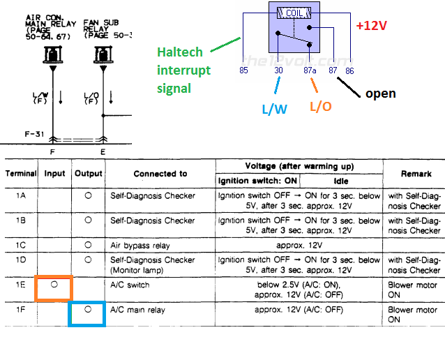
Locate the two wires I am talking about. I didn't install your Haltech so who knows where they are. They should have come from the front harness to the biggest plug that would have connected to the factory ECU. Hook your relay up like in the diagram. You are taking the L/O wire and hooking it to the normally closed pin. You are taking the L/W and hooking it to the common pin. Then the normally open pin has nothing connected to it.
So here's how it works. You press the button for the A/C. The signal goes through the factory safety switches (again see the factory wiring diagram) just like stock. The signal goes through pin 87a of the relay and out pin 30 so that it can trigger the factory main A/C relay. Now, if certain conditions are met (RPM and load) the Haltech will send a ground to pin 85 on the relay. That will trigger the coil in the relay. Normally there is continuity between pins 30 and 87a. When the Haltech triggers the relay, there will be continuity between pins 30 and 87. 87 has nothing hooked to it (open circuit) so the A/C main relay turns off and the clutch disengages--just like factory.
Use the nitrous output capability of the Haltech:
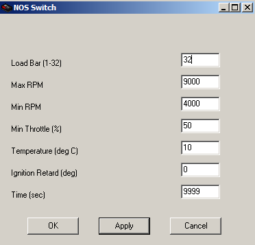
set your rpm and load trigger points at which the A/C will turn OFF. The time is maxed out in this screenshot here but you can set it to whatever timer you want.
First, check out page 50-64 of the wiring diagrams and page 4A-30 of the fuel and emissions control (non turbo) section in the FSM. There's a light blue/orange wire coming from the front harness that originally went to pin 1E. That comes from the logicon and already goes through the pressure and temperature switch. You don't need to touch those at all.
Then a light blue/white wire originally came out of the factory ECU to control A/C operation by triggering the main A/C relay. The main A/C relay controls the compressor clutch. On my old 88 GTU I used to run a Megasquirt and I just soldered those two wires together, so basically there was no ECU automatically shutting off the compressor based on rpm etc. But in hindsight I should have done it the way I am describing now. You just need to hook those two wires to a relay, and then use the Haltech to switch off the A/C signal when certain conditions are met.
Locate the two wires I am talking about. I didn't install your Haltech so who knows where they are. They should have come from the front harness to the biggest plug that would have connected to the factory ECU. Hook your relay up like in the diagram. You are taking the L/O wire and hooking it to the normally closed pin. You are taking the L/W and hooking it to the common pin. Then the normally open pin has nothing connected to it.
So here's how it works. You press the button for the A/C. The signal goes through the factory safety switches (again see the factory wiring diagram) just like stock. The signal goes through pin 87a of the relay and out pin 30 so that it can trigger the factory main A/C relay. Now, if certain conditions are met (RPM and load) the Haltech will send a ground to pin 85 on the relay. That will trigger the coil in the relay. Normally there is continuity between pins 30 and 87a. When the Haltech triggers the relay, there will be continuity between pins 30 and 87. 87 has nothing hooked to it (open circuit) so the A/C main relay turns off and the clutch disengages--just like factory.
Use the nitrous output capability of the Haltech:
set your rpm and load trigger points at which the A/C will turn OFF. The time is maxed out in this screenshot here but you can set it to whatever timer you want.
05-21-10, 01:06 PM
#3
Senior Member
Join Date: Aug 2009
Location: Los Angeles
Posts: 479
Likes: 0
Received 0 Likes
on
0 Posts
Go to the FAQ section, and pull up the FSM for the 89-91 cars. There is an extensive chapter on the air conditioning system (unlike the 86-88 manual, which has almost nothing on the AC). Everything you need is there.
The pressure switch is in front of the radiator on the right side. It closes when the freon pressure goes over about 30 lbs. There is a low temp switch (not condensation) on the airbox for the evaporator unit; it is behind the left side of the glovebox. It goes open when the evap temp goes below abt 41F, to keep it from icing up. There is a switch in the logicon, which is the AC switch on the front panel. It also is in series with a switch on the fan speed slider; it goes open when the fan is off. Finally, the ECU pulls the circuit to ground when it commands the AC on. It will turn off the AC under full throttle acceleration, but only for 7 seconds.
Unless you want to implement the full throttle cut out, you will not need to make an ECU; a switch to ground will do it.
05-21-10, 01:15 PM
#4
You don't need an ECU to control the compressor, the FC does not control the function. Set it up just as is, without the connection to the ECU. The V8 conversion guys do this all the time.
You do need the low pressure switch in front of the condenser, near the receiver drier. It prevents operation if the system is low on refrigerant.
You also need the thermoswitch, located in the evaporator housing top. It cycles the compressor to prevent the evaporator from freezing up.
The ecu only intervenes to cut out the compressor for 10 seconds if it senses that the throttle position is over 80% open. You can probably mimic this with the Haltec.
Other good controls to add might be a high pressure cut out at around 350 PSI. https://www.ackits.com/pc/57807MD/co...Cut-off+Switch Add it to the high side port. This will protect the system if your fan fails, or if you convert to R134a,
05-21-10, 07:25 PM
#5
I have known there was easy solutions. My current job is a bit more electrical hardware involved and since I am a software guy at heart I was going to use this as an opportunity to learn a thing or two. But this does look really really easy.
Decisions decisions.
Thanks a bunch btw, I am not sure I would have been clever enough to put that together
05-21-10, 07:49 PM
#6
Go to the FAQ section, and pull up the FSM for the 89-91 cars. There is an extensive chapter on the air conditioning system (unlike the 86-88 manual, which has almost nothing on the AC). Everything you need is there.
The pressure switch is in front of the radiator on the right side. It closes when the freon pressure goes over about 30 lbs. There is a low temp switch (not condensation) on the airbox for the evaporator unit; it is behind the left side of the glovebox. It goes open when the evap temp goes below abt 41F, to keep it from icing up. There is a switch in the logicon, which is the AC switch on the front panel. It also is in series with a switch on the fan speed slider; it goes open when the fan is off. Finally, the ECU pulls the circuit to ground when it commands the AC on. It will turn off the AC under full throttle acceleration, but only for 7 seconds.
Unless you want to implement the full throttle cut out, you will not need to make an ECU; a switch to ground will do it.
The pressure switch is in front of the radiator on the right side. It closes when the freon pressure goes over about 30 lbs. There is a low temp switch (not condensation) on the airbox for the evaporator unit; it is behind the left side of the glovebox. It goes open when the evap temp goes below abt 41F, to keep it from icing up. There is a switch in the logicon, which is the AC switch on the front panel. It also is in series with a switch on the fan speed slider; it goes open when the fan is off. Finally, the ECU pulls the circuit to ground when it commands the AC on. It will turn off the AC under full throttle acceleration, but only for 7 seconds.
Unless you want to implement the full throttle cut out, you will not need to make an ECU; a switch to ground will do it.
05-22-10, 09:17 AM
#7
by close he means like closed circuit. as in continuity (current will pass). open meaning open circuit, as in no continuity (current will not pass) and infinite resistance. As I mentioned, these switches are already installed in-line from the A/C button on the logicon to the stock ECU input (light blue/orange wire). As long as they were not disturbed at some point you don't have to worry about them at all.
on the one hand, projects are fun. on the other hand, keep it simple stupid
My current job is a bit more electrical hardware involved and since I am a software guy at heart I was going to use this as an opportunity to learn a thing or two.
Trending Topics
05-22-10, 11:44 AM
#8
I think I am starting to understand this a bit better. Please correct me if I am wrong!
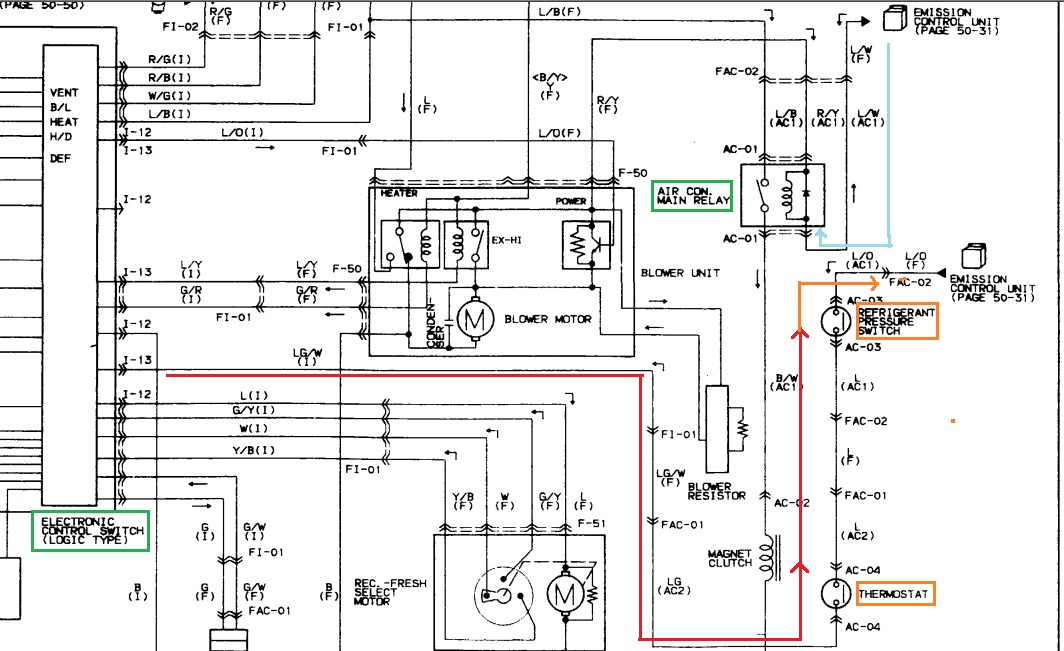
It looks to me like the L/B wire (4th from the top on the upper left hand box) is the actual A/C button from the HVAC. This is an output from the HVAC as 12V when the button for A/C is pressed.
The ECU controls I-13 LG/W (red on argh pic) and pulls it to ground when it will allow the A/C to be on. During the full throttle cutoff it pulls it to 12V, this stops the flow of current from the button 12V and turns off the magnetic clutch.
The pressure switch and thermostat control the A/C because they will break the connection of the Orange and Light-blue wires thus killing the current through the A/C main relay and break the connection of the magnetic clutch. Thus stopping A/C.
So, if all that is true I should just hook my Haltech straight to the I-13 LG/W wire and control it that way. It looks like I would still have to solder the orange and light blue wires together.
Does all that make sense?
 05-22-10, 04:52 PM
#11
I want the haltech to control it for full throttle, and for low load cutoff since I don't have an idle air controller.
Assuming I am reading this correctly, in the stock circuit when the ECU is plugged in, requires it to output a ground for the A/C to work.
Assuming I am reading this correctly, in the stock circuit when the ECU is plugged in, requires it to output a ground for the A/C to work.

Thread
Thread Starter
Forum
Replies
Last Post
NickNac113
1st Generation Specific (1979-1985)
13
10-01-15 09:25 PM