130 amp Taurus alt wiring question
 09-11-11, 04:46 PM
#1
130 amp Taurus alt wiring question
I'm looking for help from anyone who has done this swap.
After reading through the write ups available, I'm still confused on the wiring. I have the alternator physically bolted up in the car, I just cant sort out the wiring. I am not an electrical guru. If someone could please explain this in better detail, please let me know. Thanks.
https://www.rx7club.com/showthread.p...rus+alternator
https://www.rx7club.com/showthread.p...rus+alternator
 09-12-11, 07:53 AM
#4
That diagram is wrong and will cause you trouble
That is exactly what you should NOT do. There are two problems with this diagram:
1.) This wiring arrangement puts the yellow wire (S) onto the 'B' terminal. The alternator will act much the same as a 'One Wire' Alternator. Your voltage will tend to run low.
2.) Hooking the 'green wire' to the ignition switch will cause the battery to drain, just like miswiring an FD alternator!
Will the diagram you posted work? Kinda sorta, not so much. Your battery will drain when the ignition is off and your volts will run low, so the battery will not really be fully charged. Ever.
How to do it right? *sigh* I'ma gonna post this again, but it is already in the ARCHIVE.
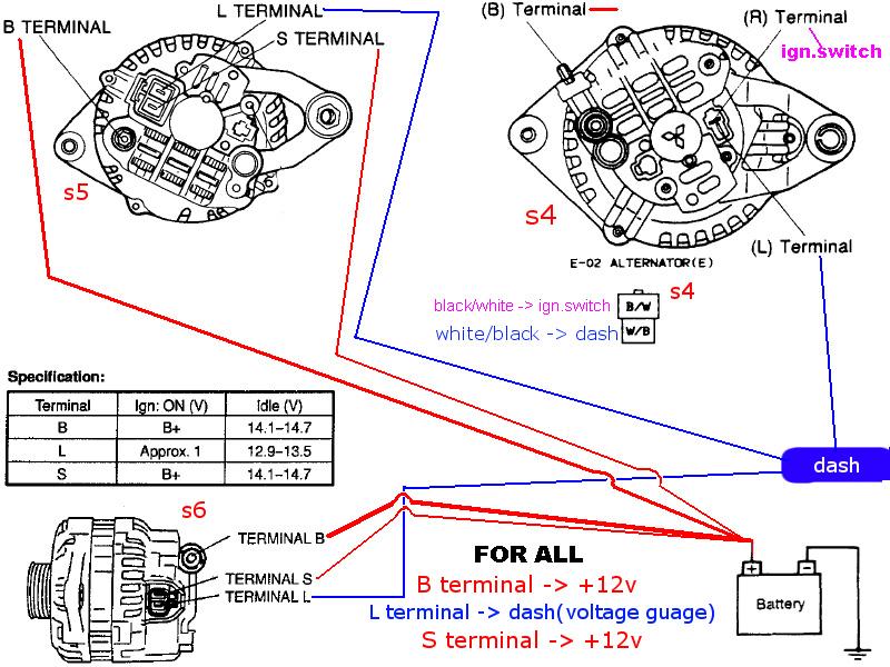
Now let me help you put this diagram into exact action on your S4:
Step 1.) On your diagram, the yellow wire is the 'S' wire. It 'senses' the voltage for the voltage regulator. This will keep the volts at 14.1-14.5 at the point you attach the wire. If you hook it to your 'B' terminal, the volts will b a 14.1 at the terminal, but volts will be lower everywhere else in the car. You need to run a new wire to your battery. This is especially important if you have a relocated battery.
Step 2.) Use the white/black wire from your original alternator harness to connect to the 'green' wire in your diagram. This allows the charging light to work.
If you have an S5:
For anyone searching for help, your S5 harness has everything you need for the Taurus alternator. Use the plug for the Taurus unit. Hook the' A' wire from your Taurus plug to the 'S' wire from your harness. Hook the 'l' wire to the 'L' terminal on your harness. If you can't read the diagram above, the 'S' wire will be the bigger of the two wires.
1.) This wiring arrangement puts the yellow wire (S) onto the 'B' terminal. The alternator will act much the same as a 'One Wire' Alternator. Your voltage will tend to run low.
2.) Hooking the 'green wire' to the ignition switch will cause the battery to drain, just like miswiring an FD alternator!
Will the diagram you posted work? Kinda sorta, not so much. Your battery will drain when the ignition is off and your volts will run low, so the battery will not really be fully charged. Ever.
How to do it right? *sigh* I'ma gonna post this again, but it is already in the ARCHIVE.
Now let me help you put this diagram into exact action on your S4:
Step 1.) On your diagram, the yellow wire is the 'S' wire. It 'senses' the voltage for the voltage regulator. This will keep the volts at 14.1-14.5 at the point you attach the wire. If you hook it to your 'B' terminal, the volts will b a 14.1 at the terminal, but volts will be lower everywhere else in the car. You need to run a new wire to your battery. This is especially important if you have a relocated battery.
Step 2.) Use the white/black wire from your original alternator harness to connect to the 'green' wire in your diagram. This allows the charging light to work.
If you have an S5:
For anyone searching for help, your S5 harness has everything you need for the Taurus alternator. Use the plug for the Taurus unit. Hook the' A' wire from your Taurus plug to the 'S' wire from your harness. Hook the 'l' wire to the 'L' terminal on your harness. If you can't read the diagram above, the 'S' wire will be the bigger of the two wires.
Trending Topics
 09-27-11, 09:01 PM
#10
Rotary Freak

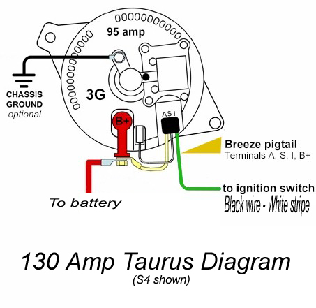
Do as you please, but if I put a Tarus alternator in my series FOUR car, I'd do it like the jpg attached.
"I" terminal on the Tarus alternaot {Green wire shown in the jpg} would go to the WHITE/black wire in the series four alternators elect plug.
"S" terminal on the Tarus alt would go just where it says in the jpg attached.
"A" terminal of the Taruns alt woudl get a new wire with a FUSE inbetween it and the battery or I'd splice it into one of the two EGI fuses on a series four car.
I reckon you know where the "B" Terminal goes.
DO NOT use the BLACK/white wire in the series four alternators electrical plug.
Note that the WHITE/black wire in the series four alt electrical plug gets fed power from the Meter fuse via the COIL of the alternator relay in the CPU and this coil of the alt relay is approx 500 ohms value. Just my way of saying if you don't use the WHITE/black wire in the series four alt plug and get the power from another source, it would not hurt to put a 500 ohm resistor in line to the OTHER source of power.
WHITE/black wire is the excitation voltage for the series four alt and that's also what the Tarus alt's "A" terminal is used for. Take heed.
09-28-11, 04:20 PM
#11
"I" terminal on the Tarus alternaot {Green wire shown in the jpg} would go to the WHITE/black wire in the series four alternators elect plug. Ignition Switched 12v Source
"S" terminal on the Tarus alt would go just where it says in the jpg attached.Loops back to Stator Terminal
"A" terminal of the Taruns alt woudl get a new wire with a FUSE inbetween it and the battery or I'd splice it into one of the two EGI fuses on a series four car.Voltage Sensor Terminal
WHITE/black wire is the excitation voltage for the series four alt and that's also what the Tarus alt's "A" terminal is used for. Take heed.
Personally, the way I'd do it is to find a decent 12v switched source for the "I" Terminal and put the "A" terminal wire on the EGI fuse as you suggested. That's how it's gonna be with my 20B FC.
09-29-11, 12:42 AM
#12
This is my social media.
iTrader: (22)
Join Date: Jan 2006
Location: WA
Posts: 2,744
Likes: 0
Received 0 Likes
on
0 Posts
I did the Taurus alternator swap using Akagi's diagram. I've never had a voltage problem since... The diagram is one of the most simple to follow and understand.
02-08-12, 03:07 PM
#13
Senior Member
iTrader: (3)

Join Date: Oct 2008
Location: Glenwood, Iowa
Posts: 447
Likes: 0
Received 0 Likes
on
0 Posts
Just for clarification, but I think I'm right in assuming an S4 has no sensing wire in the harness itself? I've looked at the FAQs and many posts about it and have seen the S4/5/6 diagram and only the S5/6 have an S terminal. I'm doing the Taurus alt swap myself right now and just would like to know the technical details.
Also, is the stock B+ wire sufficient gauge for a bone stock car? I do plan on doing the big three in 1/0 gauge or more here in the next week or so in preparation for my audio upgrade, just need to know if it would be safe until then.
Edit: ****, didn't realize the date on this thread. Sorry.
Also, is the stock B+ wire sufficient gauge for a bone stock car? I do plan on doing the big three in 1/0 gauge or more here in the next week or so in preparation for my audio upgrade, just need to know if it would be safe until then.
Edit: ****, didn't realize the date on this thread. Sorry.
02-08-12, 03:59 PM
#14
Just for clarification, but I think I'm right in assuming an S4 has no sensing wire in the harness itself? I've looked at the FAQs and many posts about it and have seen the S4/5/6 diagram and only the S5/6 have an S terminal. I'm doing the Taurus alt swap myself right now and just would like to know the technical details.
Also, is the stock B+ wire sufficient gauge for a bone stock car? I do plan on doing the big three in 1/0 gauge or more here in the next week or so in preparation for my audio upgrade, just need to know if it would be safe until then.
Edit: ****, didn't realize the date on this thread. Sorry.
Also, is the stock B+ wire sufficient gauge for a bone stock car? I do plan on doing the big three in 1/0 gauge or more here in the next week or so in preparation for my audio upgrade, just need to know if it would be safe until then.
Edit: ****, didn't realize the date on this thread. Sorry.
As for replacing the 'B' terminal wire, I did not replace the B wire on my S5. The S5 'B' wire is quite a bit larger than the S4 'B' wire. I would replace that wire if I were doing this swap on an S4.
I'm at 3.5 years and 20,000 miles with this alternator. This weekend I jump started a 24' Hino truck with no problem!
02-08-12, 05:04 PM
#15
Senior Member
iTrader: (3)
Join Date: Oct 2008
Location: Glenwood, Iowa
Posts: 447
Likes: 0
Received 0 Likes
on
0 Posts
That's what I figured, I=L and B+S go to the battery. Which unfortunately means I'm going to need to replace my stock terminal connectors as I see no way to run a new B+ cable back to the battery. I was thinking some marine terminal connectors and just putting a ring terminal on my stock pos. and neg. wires. Would that work or is there a simpler way? Only thing I imagine is that it would make adding new wires quite a bit easier when/if I needed to.
02-08-12, 05:19 PM
#16
This is my social media.
iTrader: (22)
Join Date: Jan 2006
Location: WA
Posts: 2,744
Likes: 0
Received 0 Likes
on
0 Posts
This is all posted above in the diagrams. Series four connector has two wires. B/W (ignition) which is the "R" terminal, and W/B (dash) which is the "L" terminal.
Yes, the stock B+ wire should be fine. I use it with no issues.
1/0 gauge!? How big of an "audio upgrade" are you doing??
This should explain everything for the Taurus alternator to be wired in a series four car...
Yes, the stock B+ wire should be fine. I use it with no issues.
1/0 gauge!? How big of an "audio upgrade" are you doing??
This should explain everything for the Taurus alternator to be wired in a series four car...
Last edited by dwb87; 02-08-12 at 05:23 PM. Reason: Oops, started writing this post about two hours ago, came back and hit "Post quick reply". Sorry to seem so repetitive.
02-08-12, 06:08 PM
#17
Senior Member
iTrader: (3)
Join Date: Oct 2008
Location: Glenwood, Iowa
Posts: 447
Likes: 0
Received 0 Likes
on
0 Posts
Well, I've got about 20' of 1/0 left from a few other audio installs, so why not? Now, I'm getting conflicting info, jackhild says I=L and you say I=R, it's just back and forth between all the different threads I've read. I thought the dash light/resistor circuit was used to ground out the coil for the field relay in modern cars/alternator, according to my school books. But, that does not mean I know how the 7 is doing things. Dammit, if I had a spare 7 alt sitting around...
02-08-12, 09:08 PM
#18
This is my social media.
iTrader: (22)
Join Date: Jan 2006
Location: WA
Posts: 2,744
Likes: 0
Received 0 Likes
on
0 Posts
If I remember correctly, HAILERS or satch may have also mentioned to use the W/B wire for the "I" terminal. I currently use the B/W wire. I need to read more into this... Perhaps HAILERS or satch could chime in.


 05-21-16, 03:53 AM
#22

bringing up old thread but I just installed using the above ^^ diagram, just confirming it works!!
"I" green wire to the white/black harness wire just like an s5 or s6 alternator is wired and your good to go.
"I" green wire to the white/black harness wire just like an s5 or s6 alternator is wired and your good to go.
Last edited by J DUBB; 05-21-16 at 03:57 AM. Reason: added to post
10-26-23, 01:12 AM
#23
Full Member

So here I am in 2023, all the pictures of the bad ways to route this are still hosted, while all the good images have vanished so am getting a bunch of "look at this" followed by blank spaces.
Does anyone happen to have the good images still saved for the proper way to wire this to a S4? At least just to make sure that future searching does not have this happen again?
Does anyone happen to have the good images still saved for the proper way to wire this to a S4? At least just to make sure that future searching does not have this happen again?
10-26-23, 10:14 AM
#24
Senior Member
iTrader: (3)
Join Date: Oct 2008
Location: Glenwood, Iowa
Posts: 447
Likes: 0
Received 0 Likes
on
0 Posts
So here I am in 2023, all the pictures of the bad ways to route this are still hosted, while all the good images have vanished so am getting a bunch of "look at this" followed by blank spaces.
Does anyone happen to have the good images still saved for the proper way to wire this to a S4? At least just to make sure that future searching does not have this happen again?
Does anyone happen to have the good images still saved for the proper way to wire this to a S4? At least just to make sure that future searching does not have this happen again?
Edit: Maybe I'm confused, I'll check it tonight when I get home if I remember.
Last edited by 88_N/A_GXL; 10-26-23 at 10:19 AM.
10-26-23, 11:44 AM
#25
Full Member
Issue is that image that dwb87 is the exact same image in post 3 that Hazard15301 posted that was said to be incorrect in post 4 and can cause slow drainage of the battery. https://www.rx7club.com/2nd-generati.../#post10782942
All of the proper diagrams are not showing
All of the proper diagrams are not showing