Tfidfis
 09-13-10, 08:26 AM
#101
Waffles - hmmm good
Thread Starter
iTrader: (1)
Small update
The other day I made the mistake of starting the car to move it out of the garage
and shutting it down immediately after. You know what happened the next time
I got in it to go somewhere? Thats right it was flooded.
I'm thinking, "Damn, gotta pull the plugs SOB!" but then I decided to try starting
it. I wanted to see if this new ignition of mine could deflood an engine. So I started
cranking. The first 3 tries, nothing. The next two tries, lots of pops and backfires,
really wierd sounding like it was timed wrong. The 6th try it started and idled for
a few seconds and then the 7th try it started right up and burbled along fine.
Meanwhile I could feel the battery starting to loose its charge. With my previous
ignition I would never have gotten it started and my battery would have been
dead.
 09-13-10, 09:44 PM
#102
Actin Like I'm Drunk
iTrader: (4)
Join Date: Jul 2007
Location: Charleston, South Carolina
Posts: 1,663
Likes: 0
Received 0 Likes
on
0 Posts
Just to simplify the chart since I'm a picture learner.
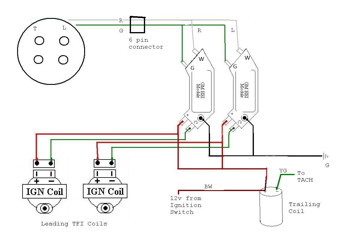
But the six pin connector color wiring is right for the SA dizzy? So that means I'd have to reverse it when I swap to a FB dizzy? I have a little head ache right now and I'm trying to make sure I got everything clear. And you just totally remove the leading coil and run your power the trailing correct?
But the six pin connector color wiring is right for the SA dizzy? So that means I'd have to reverse it when I swap to a FB dizzy? I have a little head ache right now and I'm trying to make sure I got everything clear. And you just totally remove the leading coil and run your power the trailing correct?
09-14-10, 06:48 AM
#103
talking head
I was using the 4 prong "high output" HEI's on the red 7, and it had the same issue. Try swapping the polarity on the igniters and try again. That cured mine. Found out later that they will run either way, but at higher rpms, the advance is wrong if you have it one way, wish I couls explain it in more detail, but I honestly can't recall the reasoning, just that it worked.
If anyone using the 4 pin HEI modules on a rotary could comment
that would be great. Do you experience breakup above 5 or 6K?
Would after market modules work better?
that would be great. Do you experience breakup above 5 or 6K?
Would after market modules work better?
and i will reply with quotes from my own posts i have written elsewhere previously,, answers contained within
BTW,, i have been a DLIDFIS fan for years ( mid 90's ! ) ,, have set it up many times, with many coils and versions of igniter
,,, PS,, i run trailing deleted DLIDFIS in my FC , on a half locked 12at dizzy ( with LPG fuel and turbo )
to which you can all consider --
as such, i can use the trailing pickup to send signals to fire my leading only coils
- principally to use the trailing boost retard pot
its further sweeping in its range of movement than the leading pot
( i have more vac advance, and more boost retard )
and best of all, i can adjust the timing by pulling on the trailing pot !!!
( the old split adjuster )
bloody handy when FC and Dizzy with PS bracket making dizzy base hard to change !
( BTW check out the latest versions of the HEC coils to those in your pics )
the following are all my quotes,, i can produce the entire condensed versions if you require
( some are on ausrotary,, some are saved from a defunct perth forum )
in regards to the s1 dizzy with its reversed direction reluctor vane
( and the igniter mentioned is the 4 wire bosch 024 ( or originally 021 ) or generic branded other )
my tip to one and all, particularly if confronted with s1 dizzy
ALWAYS check connection trigger polarity with a timing light
( simply redo the timing to be sure any inadvertent change in falling to rising edge signal has altered timing )
simply swap wires 6 ( sometimes 3 ) and 7 to re- reverse the signal
specifically check for a crossfire inducing the trailing to spark with the leading
( the dizzy button will only line it to the right chamber fortunately )
if you cant set the trailing timing
- and it appears to shift with the leading , its cross-firing
- the fix is usually swapping ( on s1 dizzy at least ) the trailing igniters 6 ( 3 ) and 7 wire
( but be aware the strong spark is prone to making inductive timing lights also pick up false signals, spread your leads , and get good ones )
-- dwell V output
in comparison the bosch BIM024 DFI for leading mod on a dizzy
has a lower than optimum fixed dwell for some of the rpm range
-to allow the dwell to be time optimised for the 4000- 9000 rpm range
( where the rotary really needs it to be at its best for power, not like OEM is down low for emissions )
at 9000 rpm the internal igniters fixed dwell period is about 80- 90% of the period between triggers
( investigation shows a 2.9 - 3.1 ms period is typical of that igniter )
the bosch BIM024 igniter loses out on the shorter average charge period at lower rpm
( to an ECU with a 3.25 fixed period, or to a duty dwell igniter or ECU )
but they begin to win when the available period time drops lower
and are ranged well for 4000 - 9000 rpm on a wastespark 4 cyl/ rotary
( and they win cause not many J109's are actually working like they where made 30 years ago )
the low down loss is not so bad as you think---
introducing wastespark has much reduced the low down unburnt hydrocarbons
and much improved many driving characteristics
- and they are better gains that a single long charge spark can bring
if you have bosch BIM 024 and HEI HEC coil in DFI mode
- MEC will outperform the HEC above 8500 rpm ( but not below it )
[ stephen you have dual MEC for leading coil ]
-------------------
the important point -
if ringing out a bridge past 9000 rpm on an ECU or with a J109 igniter type DFI mod
( wastespark leading application )
- you need the MEC, as it outperforms the HEC in any wastespark application above 8500 - 9000 rpm
any ECU running fixed dwell period should be brought below 3.0 ms above 9000 rpm
( or you may need to impose a 9000 rpm limit )
or retain the HEC coil combo, and revert to full sequential ignition
( reverting to duty dwell will optimise some of the losses down low when taking away the wastespark )
if wastesparking, be aware whats going on at 9000 rpm in the ignition !
Info from Bosch, raped from net
the details are not easy to find on the HEC C core coils or BIM024 !
peak primary voltage V rise times typical of a HEC coil
( time needed at that voltage to achieve maximum saturation for peak spark )
10.5 V =3.1 ms
12.0 V =2.6 ms
13.0 V =2.3 ms
13.5 V =2.2 ms
14.0 V =2.1 ms
14.2 V =2.0 ms
16.0 V = 1.7 ms
some more important BIM024 considerations when used with reluctor dizzy =
the BIM024 fire the coil on a 0.7 V zero crossing from a positive to negative trigger
( a falling reluctor pulse )
this is important to note, as incorrect phase polarity will shift the timing significantly at low rpm
ie
triggering on the rise will be dependent on the voltage raised
( and that is RPM related in a reluctor system )
so incorrect polarity will not only mean a significant timing shift
( which can be corrected with a timing light )
but also makes for an erratic trigger that moves with rpm at low dizzy speeds
- the HEI BIM024 module ( when its polarity is correct )
is intended to shift timing with decreasing dwell time and rising voltage ( RPM )
this is to maximise the dwell period at higher RPM
( its a angle based dwell system )
getting the signal polarity thing wrong will make for a system that shortens the dwell at higher RPM , and retards timing
what does that mean??
incorrectly polarised from the reluctor for its trigger signal
the BIM024 will have a timing shift at low RPM that requires the dizzy be reset to relocate the timing to the mark
also the timing point will drift as a result of
1: the air reluctor gap ( the volts generated by the reluctor )
2: also with the input voltage ( cranking )
3 :also the dizzy rpm ! ( irrespective of the centrifugal and vacuum advances )
when revved hard, its spark volts will drop away as the dwell period shortens
and it will pull timing at revs
- 1 degree every 1000 rpm
and there is method to check and combat it
( and you can also flip the reluctor vane by knocking out the roll pin to correct it )
and equally reluctor air gap is important
( and that J105 is obviously polarised oppositely to the J109 )
then you may wish to build the dizzy to utilize the timing drift appropriately to advantage
- especially if your ported a little ( or a lot )
so.. half locking the dizzy -
if, for example
i am trying things on my extend port LPG 13b
- currently modified , the dizzy has 40% of its curve trimmed
this allows me to work things thus ( mech numbers only )
40% x 25 = 10 degrees removed = 15 degree curve
set at 10 BTC degrees idle , my max timing without vac input would be 25 BTDC
( about what most mad extend port petrol engines would enjoy )
i think i want more boost
and knowing LPG likes high initial advance, but same or similar endpoints to petrol for optimum power
( rather than ping limited )
i would like to try things with 22- 23 degree endpoint
( allowing another 2 to 4 psi safety ceiling )
BUT without dropping my aggressive initial timing
- so
50% x25 = 12.5 degrees advance
so, 10 idle, 22.5 max
here-

the dizzy

a pile of indiscriminate screws, actually they all have a place, remember what they are
everything comes out, a screwdriver is all you need
( don't forget the one down centre of shaft , that ones hard )
the trailing pot arm is also fixed in by screw type fitting
remove the pots and the igniter modules
( mine are dummies for bridging through the BIM igniters )

its the weights that are the magic
bending in those spring posts has altered the spring rate, speeding it up
( you can get at them with thin screwdriver via top of assembled dizzy to adjust later )
the little nubs on top ride in our advance slots
- it really is very simple under there

our old advance slots, you can see i had previously altered them permanently, i wanna try a little more
( if you just use a washer cut into moons, it will be easily reversed on the belt sander )

OK, things at 50 % now, using the washer moon method

touch her up on the belt sander , you don't have much room to leave any tac weld high
touch her up more, and i can undo my move !

slam it together
( if gumby, mark things first before disassemble , but you find things more or less line up without much thought )
i am trying things on my extend port LPG 13b
- currently modified , the dizzy has 40% of its curve trimmed
this allows me to work things thus ( mech numbers only )
40% x 25 = 10 degrees removed = 15 degree curve
set at 10 BTC degrees idle , my max timing without vac input would be 25 BTDC
( about what most mad extend port petrol engines would enjoy )
i think i want more boost
and knowing LPG likes high initial advance, but same or similar endpoints to petrol for optimum power
( rather than ping limited )
i would like to try things with 22- 23 degree endpoint
( allowing another 2 to 4 psi safety ceiling )
BUT without dropping my aggressive initial timing
- so
50% x25 = 12.5 degrees advance
so, 10 idle, 22.5 max
here-
the dizzy
a pile of indiscriminate screws, actually they all have a place, remember what they are
everything comes out, a screwdriver is all you need
( don't forget the one down centre of shaft , that ones hard )
the trailing pot arm is also fixed in by screw type fitting
remove the pots and the igniter modules
( mine are dummies for bridging through the BIM igniters )
its the weights that are the magic
bending in those spring posts has altered the spring rate, speeding it up
( you can get at them with thin screwdriver via top of assembled dizzy to adjust later )
the little nubs on top ride in our advance slots
- it really is very simple under there
our old advance slots, you can see i had previously altered them permanently, i wanna try a little more
( if you just use a washer cut into moons, it will be easily reversed on the belt sander )
OK, things at 50 % now, using the washer moon method
touch her up on the belt sander , you don't have much room to leave any tac weld high
touch her up more, and i can undo my move !
slam it together
( if gumby, mark things first before disassemble , but you find things more or less line up without much thought )
i hope this may answer some of the unanswered questions you have posed,, despite its disjointed origins
Last edited by bumpstart; 09-14-10 at 07:02 AM.
09-14-10, 07:12 AM
#104
Waffles - hmmm good
Thread Starter
iTrader: (1)
Just to simplify the chart since I'm a picture learner.
But the six pin connector color wiring is right for the SA dizzy? So that means I'd have to reverse it when I swap to a FB dizzy? I have a little head ache right now and I'm trying to make sure I got everything clear. And you just totally remove the leading coil and run your power the trailing correct?
But the six pin connector color wiring is right for the SA dizzy? So that means I'd have to reverse it when I swap to a FB dizzy? I have a little head ache right now and I'm trying to make sure I got everything clear. And you just totally remove the leading coil and run your power the trailing correct?
using it. Just run the power directly to the ignitors and hook your tach to one of
the C terminals of the 4 pin and your set. Once you start wiring it up you'll realize
how simple it is.
If you get strange behavior when you first startup, just switch the dizzy signal by
swapping G and W. When its backwards you will see it break up around 5K if I
remember right.
09-14-10, 07:27 AM
#105
talking head
and an interesting footnot from the mopar guys concerning the HEI module operation,, and also the ford and GM " E" core coils
The Mopar system uses the positive temperature coefficient of the ballast resistor to regulate the primary coil current with changes in duty cycle (engine rpm). A simple, relatively reliable system for most daily drivers. The disadvantage with the ballast resistor is the slow response time of the resistor resulting in the field of the coil not being fully charged during sudden acceleration ie, a spark that may not be as hot as is possible with more modern systems. The GM HEI module is typically based upon a Motorola (now Freescale) MC3334 IC or equivalent. The MC3334 regulates coil current using an internal variable voltage reference. This internal variable voltage reference is able to respond much faster to changes in duty cycle resulting in a much hotter spark durring times of sudden acceleration and less destructive heating to the coil during low rpm operation. The MC3334 also imposes a 1 msec off time to ensure complete discharge of the coil field during a spark event. At very high rpms coil current is limited due to the slope of the coil's primary charging ramp time which is determined by VBatt and the primary impedance of the coil itself. Some good OEM coils are the Ford "E" core coils and the remote GM coil which is also an "E" core design. The MSD Blaster line of aftermarket coils are also very good coils. Don't be fooled by claims of HIGH VOLTAGE from the perveyors of coils. The voltage developed by the coil will only be as high as the break-over voltage of the plug firing, typically only a few thousand volts. When shopping for coils it is important to look for a coil with a high Joules rating and match the rpm range to your needs. If the coil manufacturer does not publish the joules rating of the coil, walk away and buy somewhere else. Don't use a race only coil on the street. It will just overheat and fail.
09-14-10, 07:35 AM
#106
Waffles - hmmm good
Thread Starter
iTrader: (1)
just found this thread
and i will reply with quotes from my own posts i have written elsewhere previously,, answers contained within
BTW,, i have been a DLIDFIS fan for years ( mid 90's ! ) ,, have set it up many times, with many coils and versions of igniter
,,, PS,, i run trailing deleted DLIDFIS in my FC , on a half locked 12at dizzy ( with LPG fuel and turbo )
to which you can all consider --
i believe you have another form of DLIDFIS,, simply with the DFI coils other than HEI ones
( BTW check out the latest versions of the HEC coils to those in your pics )
the following are all my quotes,, i can produce the entire condensed versions if you require
( some are on ausrotary,, some are saved from a defunct perth forum )
in regards to the s1 dizzy with its reversed direction reluctor vane
( and the igniter mentioned is the 4 wire bosch 024 ( or originally 021 ) or generic branded other )
a lot of internet searching and reading before I came up with it. It really is just
another flavor of DFIS though, but the goal I had was to be able to do this easily,
cheaply and re-source replacements in the field easily. So a little bit different
audience and focus from what you ended up doing. Your setup sounds like its
working well for you and its great that your sharing this here. We all appreciate it.
I preferred to fix the s1 dizzy issue by getting an s2 dizzy which has the right
polarity to begin with and has a better signal due to its shape. Until I did this
mod I didn't realize the s1 and s2 dizzy reluctors were radically different.
I had read the specs on the HEI modules and realized they had issues at
higher rpms but my engine will never see those extremes so I didn't
investigate further. The TFI coils seemed like the better alternative to the
HEI coil just due to the fact that I was getting them from the junkyard and the
HEI coils are usually on the dizzy in the heat and the TFI coils on the Ford 150
trucks sit away from the heat, on the inside fender. I still had to ohm out a few
until I got 2 that were like new.
I can see that if your doing this on a high rpm bridge or PP port you really
need to deal with the dwell characteristics and timing issues. Interesting how
you repurposed the trailing dizzy signal to use its wider adjustibility.
09-14-10, 08:42 AM
#108
talking head
note also that your generic 4 pin module is not self adjusting dwell
( but bim024 and your 7 pin unit is )
also,, bim024 and the 7 pin unit is a positive to negative trigger ,, and your 4 pin module is negative to positive
( but bim024 and your 7 pin unit is )
also,, bim024 and the 7 pin unit is a positive to negative trigger ,, and your 4 pin module is negative to positive
09-14-10, 08:57 AM
#109
Waffles - hmmm good
Thread Starter
iTrader: (1)
modules I have to see how they work now that I fixed the dizzy issue. The 7
pins are much easier to find in the junkyards, dime a dozen. The 4 pins, not
so much, they get picked clean very quickly from the donors.
09-18-10, 09:27 AM
#110
Full Member

Hi folks, awesome thread so much so I built this for my RX-2 last night. Having some issues and wondering if you could lend some advice. :-)
Later model distributor with the later reluctor wheel (hope that is correct terminology!), N322 stamped on side. TFI coils, GM HEI (well the UK equivalent from a Jag) etc as documented here and other threads. Soldered directly to the red/green wire in the distributor, my 109's are good :-) Not shielded but twisted as the info suggested shielded wire is not required. I have reversed the red/green to HEI module connections from the original here so RED goes to G and GREEN goes to W. (Reversed she runs lumpy and misfires a little)
Vacuum advance disconnected, mechanical still used. Static timing set to TDC and tweaked a little to start, no problem (street ported). When I go to time the leading, as I load up the revs to get to max advance the timing marks are erratic and not smooth like I see on the trailing. Additionally, start to advance but then starts to jump and retard back towards the TDC and earlier BTDC marks I have on the pulley! Timing light at very high rev starts to become erratic and cut in and out also.
I have checked all the wiring many times and as I mention, car runs and revs nicely sat in garage. So what gives why is my trailing advancing nice and smoothly as I would expect but my leading is playing up? Any thoughts please? The only thing I can now think of is my mechanical advance for the leading is sticky and misbehaving?
Look forward to hearing any thoughts as I put the kettle on and strip the dizzy :-)
Many thanks
Ant
09-18-10, 01:10 PM
#111
Waffles - hmmm good
Thread Starter
iTrader: (1)
reluctor signal has to go directly to the HEI, not thru the J109s. Maybe I'm just
misunderstanding something here.
I know the HEIs in the Jag are very similiar, having read about them when I
researched this mod. Only thing I can think is to reverse the red and green
connections to the HEIs but you did that. Also did you ground the HEIs good
and correctly (on the screw hole with the extra metal collar around it). I bad
ground can cause the HEI to not read the reluctor signal correctly.
Recheck all your wiring and leave the trailing off to isolate things further.
09-18-10, 11:16 PM
#112
talking head
methinks he has J109 driving HEI coils directly,, no bosch BIMs
from this info,, i suggest one of the J109's is erratic at revs,, try swapping them to see if the problem persists but now on the trailing
also,, if setting up the leading, try disconnecting the trailing igniter to be certain there is no cross trigger for your timing light
( triggering on EMF from the trailing )
the retard at revs does however suggest some polarity issue,, are both leadings J109,, or is there a j105 in this system
( i rather suspect the j105 works in reverse polarity to the j109 )
PS
sometimes an internal ground strap is required inside the dizzy ( race to outer case ) to stabilise the triggers
Last edited by bumpstart; 09-18-10 at 11:19 PM.
09-19-10, 09:44 AM
#113
Waffles - hmmm good
Thread Starter
iTrader: (1)
Well hopefully he will get back to us. I read it as TFI coils with Jag HEI
ignitors (clone of the GM 4 pin HEI). But he then mentions that his
j109s are good which threw me. Maybe he left the j109s in the circuit
between the reluctor and the HEIs and that would definitely not work
well.
ignitors (clone of the GM 4 pin HEI). But he then mentions that his
j109s are good which threw me. Maybe he left the j109s in the circuit
between the reluctor and the HEIs and that would definitely not work
well.
09-19-10, 10:50 AM
#114
Full Member
Thanks for the replies guys. The Leading is to the HEIs without the J109, J109 still for trailing currently. I have disconnected the trailing totally and still see this occurring on the leading. Tried 2 dizzys, one directly soldered to the red/green the other, connectors directly to the plug the J109 mounts to.
Yes grounded to the HEIs directly. I did reverse the red/green again and the timing is way out, don't even see the timing marks? 180 degrees out?
I tried with my spare dizzy and see exactly the same occurring. I stripped and rebuilt dizzy too, it was a tad dried out and sticky but this made no difference. Swapped out HEIs in case faulty and exactly the same.
09-20-10, 10:28 AM
#116
Full Member
Thanks Bumpstart, it was only fractionally off this but again no change, I even tried screened cable to the modules with no change. Ordered new plugs and Magnecor coil leads today to rule these out. Beyond that getting a little stumped.
I am assuming with a normal non-fancy timing light (i.e. no dials and *****) as used before, I should still be able to set the leading timing accurately and see it advance smoothly? I did read some lights cannot keep up and very high RPM.
Thanks
I am assuming with a normal non-fancy timing light (i.e. no dials and *****) as used before, I should still be able to set the leading timing accurately and see it advance smoothly? I did read some lights cannot keep up and very high RPM.
Thanks
09-20-10, 11:38 AM
#117
Waffles - hmmm good
Thread Starter
iTrader: (1)
I just have an old SunPro timing light, no adjustibility or anything. Works fine for
seeing the timing.
What exactly are you using for the HEI ignitor? You mention some Jag stuff.
Post up the specs or model so we can see what the specs are. Maybe what
you have is not speced the same or has some additional behaviour.
seeing the timing.
What exactly are you using for the HEI ignitor? You mention some Jag stuff.
Post up the specs or model so we can see what the specs are. Maybe what
you have is not speced the same or has some additional behaviour.
09-20-10, 01:04 PM
#118
Full Member
*Sigh* so I have been speaking to another local parts supplier who is now saying the Jag one (ref = QHLXEI8 in the UK) is *not* a GM HEI type after the original parts supplier took a week to tell me it is!
Back to square one :-) So this time I will order direct from Jeggs/Summit. From memory in this thread it was mentioned that the 7 pin modules might actually be better than the 4 pin ones, was this ever concluded?
I assume the ones here will suffice and as people have previously mentioned no need for the 'performance' versions of these:-
http://www.jegs.com/p/Accel/Accel-Di...49295/10002/-1
Thanks for the guidance :-)
Ant
09-20-10, 01:27 PM
#119
Waffles - hmmm good
Thread Starter
iTrader: (1)
Glad you found the problem or what looks like the problem.
The 7 pins should work fine. I initially had the 7 pins hooked up but went to brand
new 4 pins while debugging. I just left it that way afterwards. I picked the 7 pins up
in the junkyard for almost nothing. Note as bumnstart said the inputs are reversed
polarity on the 7 pins and you still only use 4 of em.
One of my previous drawings has the wiring for the 7 pins as well.
09-23-10, 11:09 AM
#121
Full Member
New GM modules arrived today, fitted and all is good - very glad I did this mod well worth it :-) Thanks again for the assistance guys, appreciate it. Lesson is don't believe people when they tell you cross reference part numbers.
Thanks
Ant
Thanks
Ant
10-13-10, 08:32 AM
#123
just have a couple of questions for you guys.
First of all, just verify if i have the diagram right, i used to go by jeff20b's geocity website but it's not up anymore. i have an 81+ dizzy and a 4 pin HEI. so Green wire goes to "W" and Red wire goes to "G." "B" stays positive (+) and "C" stays negative (-). right?
First of all, just verify if i have the diagram right, i used to go by jeff20b's geocity website but it's not up anymore. i have an 81+ dizzy and a 4 pin HEI. so Green wire goes to "W" and Red wire goes to "G." "B" stays positive (+) and "C" stays negative (-). right?
10-13-10, 09:19 AM
#124
Waffles - hmmm good
Thread Starter
iTrader: (1)
Dizzy G goes to HEI W
Dizzy R goes to HEI G
HEI B is connected to positive as is the coil +
HEI C goes to coil -
HEI has to be grounded thru one of the installation screws ( the one with the collar on it)
Depending on the Dizzy used the G and W connections may be reversed. For the
FB dizzy I think whats above is correct.
The following users liked this post:
midnight mechanic (07-16-21)
 . couldn't remember off the top of my head

