(IGNITION) DLIDFIS installed! Small write-up and some questions

 09-03-04, 02:58 PM
#52
It came from a bad dizzy.

Yeah, the MSD's purple wire goes to the pickup's green wire. It seems backwards, but I ended up memorizing it that way so I've never had a polarity problem when dealing with my MSD on my project oh so many years ago.
By the way, I'm working on a post where the pics will have captions. I mentioned something about keeping the polarity/color coding of the pickup plugs' wires up through the T shaped connector at the top of the ignitor. It's something like Red=Right when it's installed... you'll see it.
slashdawg, it's a size 104 hose clamp and it's just a little on the long side for Mazda coil holders. I size 102 or 100 (possibly even a 90-something) would be better.Infact, I had to tighten my very last one all the way down and add an extra piece of radiator hose to help snug up the third coil in my friend's 77 REPU because it has a 1st gen upper coil holder piece instead of the stock points style his truck originally came with. You can probably see the ballast resistor holder in some of my pics. This actually helps to stabilize the third coil in REPUs. The Cosmo was a little different and required two hose clamps.
09-03-04, 03:13 PM
#53
The relay takes power from the starter solenoid's thick battery wire and routes it up to the ignitors and coils. Since it's always electrically on, you need a relay to act as a switch which is remotely controlled by the existing ignition wire(s). Since an RX-7's battery is usually up in the engine bay, a relay is actually easier to install than in an REPU. My Cosmo should be pretty easy as well. The battery is under the bed on the opposite side of the gas tank in an REPU (having no clunky battery in the engine bay is awesome! Although a little inconvenient at times).
09-03-04, 03:52 PM
#54
And now for your viewing pleasure, here are all the pics complete with captions.
Let's start off by looking at my DLIDFIS wiring diagram. This is usually all anyone needs in order to wire up DLIDFIS on their rotary.
Legend:
1 battery
2 ignition switch
3 Leading coils
4 Leading ignitors
5 Leading magnetic pickup inside distributor
6 Trailing coil
7 Trailing ignitor
8 Trailing magnetic pickup inside distributor
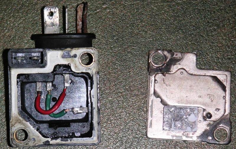
Here is my gutted ignitor with color coded wires soldered to the pins. Notice how the pins are jumpered. This allows the red and green wires to stay in the same positions; green is on the right-hand pin when viewed from the back. In other words, when the gutted ignitor is installed, the red wire will be on the right-hand side of the T shaped connector at the top of the ignitor. Red=Right. This is my prefered wiring method and is very easy to remember IF you jumper the pins as I have done.
Left, typical ignitor plate for DLIDFIS. On right, a single ignitor for a custom ignition system I'm working on.
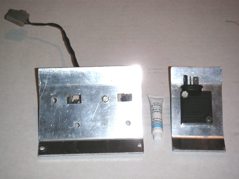
The backside of the ignitor plates.
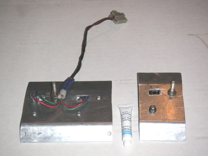
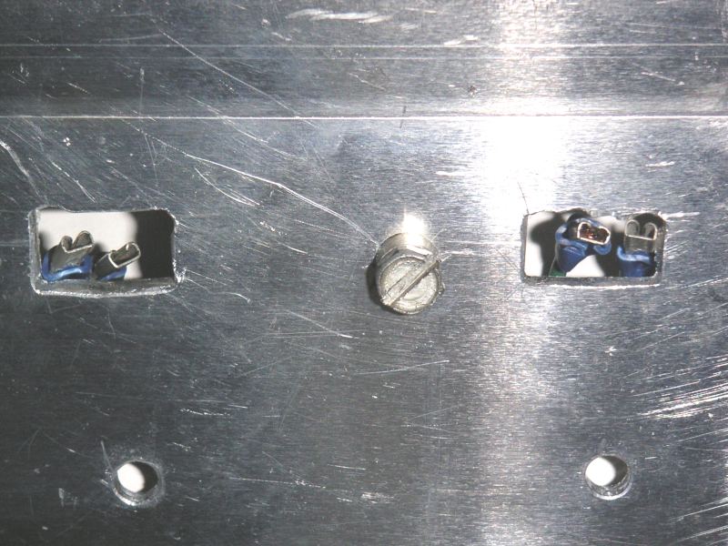
Closeup of DLIDFIS ignitor plate. This was once in my 13B powered GLC and fits in the stock external voltage regulator location. It worked great.
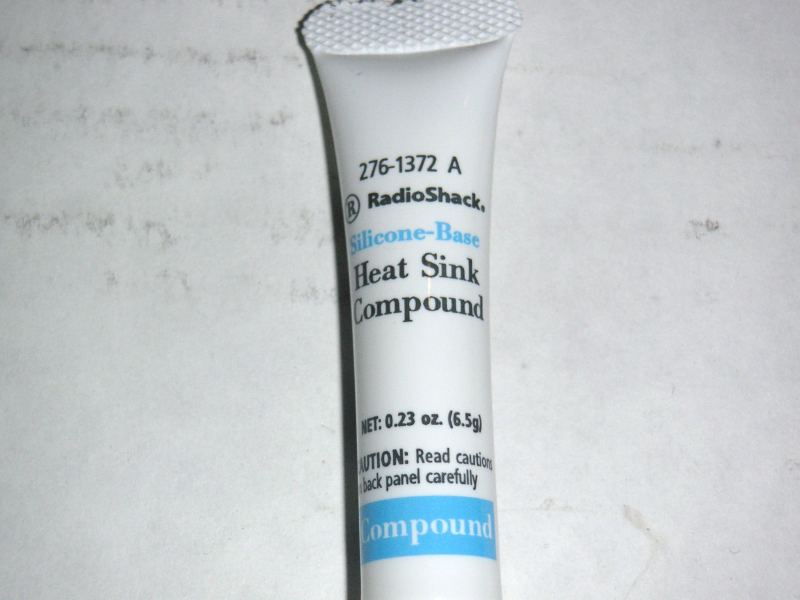
Closeup of the heat sink Compound from Radio Shack.
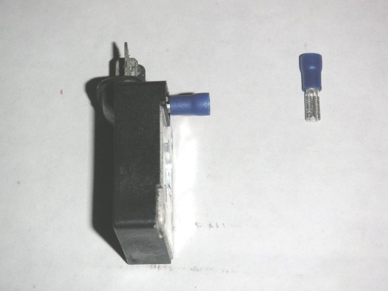
Tweeter connectors that have been opened slightly to better fit the pickup pins. I usually push them on as deep as in this picture. I've never had one fall off, yet they're still possible to remove with limited working space. It's good to find a balance of snugness.
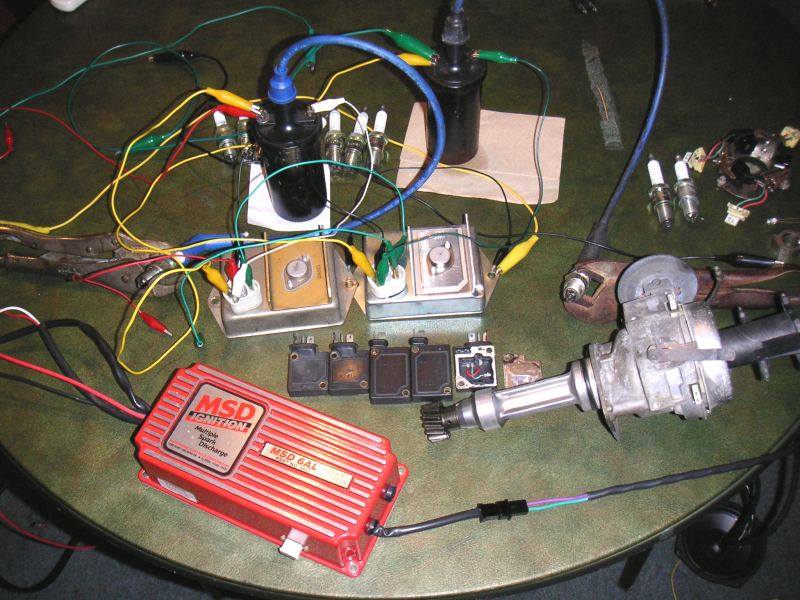
Bench testing some Mopar ignition modules here. The MSD, Mazda ignitors and dizzy are only in this picture for the sake of human interest.
Let's start off by looking at my DLIDFIS wiring diagram. This is usually all anyone needs in order to wire up DLIDFIS on their rotary.
Legend:
1 battery
2 ignition switch
3 Leading coils
4 Leading ignitors
5 Leading magnetic pickup inside distributor
6 Trailing coil
7 Trailing ignitor
8 Trailing magnetic pickup inside distributor
Here is my gutted ignitor with color coded wires soldered to the pins. Notice how the pins are jumpered. This allows the red and green wires to stay in the same positions; green is on the right-hand pin when viewed from the back. In other words, when the gutted ignitor is installed, the red wire will be on the right-hand side of the T shaped connector at the top of the ignitor. Red=Right. This is my prefered wiring method and is very easy to remember IF you jumper the pins as I have done.
Left, typical ignitor plate for DLIDFIS. On right, a single ignitor for a custom ignition system I'm working on.
The backside of the ignitor plates.
Closeup of DLIDFIS ignitor plate. This was once in my 13B powered GLC and fits in the stock external voltage regulator location. It worked great.
Closeup of the heat sink Compound from Radio Shack.
Tweeter connectors that have been opened slightly to better fit the pickup pins. I usually push them on as deep as in this picture. I've never had one fall off, yet they're still possible to remove with limited working space. It's good to find a balance of snugness.
Bench testing some Mopar ignition modules here. The MSD, Mazda ignitors and dizzy are only in this picture for the sake of human interest.
09-03-04, 03:53 PM
#55
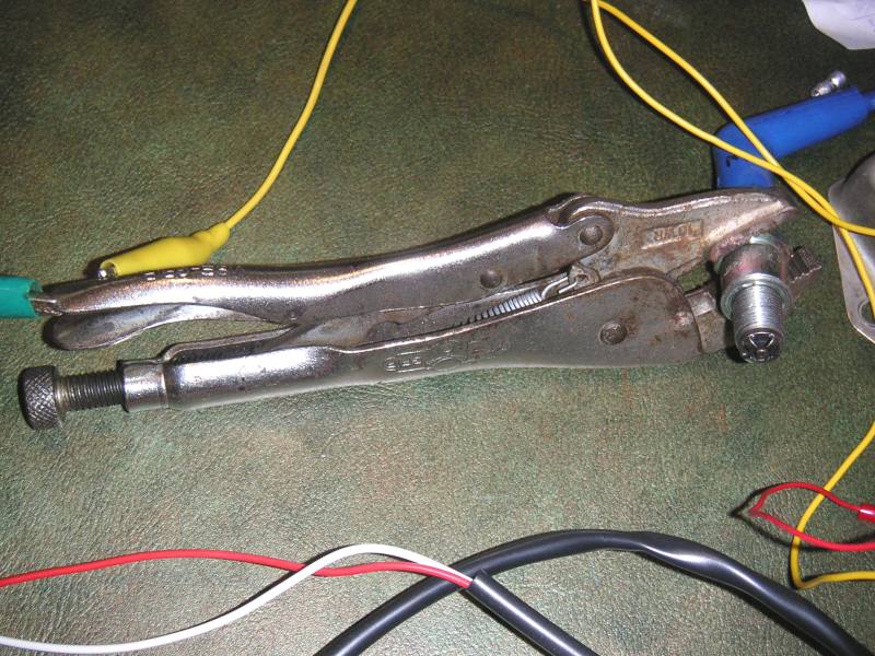
Vice Grips or other locking pliers are great to ground spark plugs. They only need to be tight enough to gently hold the spark plugs. Then use aligator clips or whatever to electrically ground it to your power source. I tested four sets of spark plugs (16 total) in no time at all.
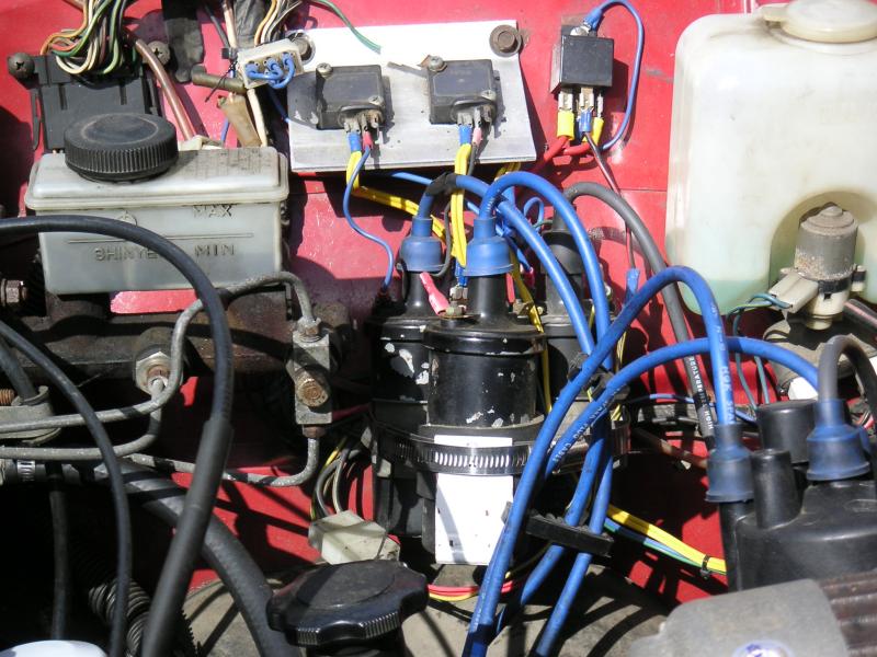
My white REPU. It had an external voltage regulator at first so I had to move the aluminum plate over a little compared to my red REPU. I later swapped in an internally regualted alt so I could then remove the external reg. I installed a relay at one of the old voltage reg bolt holes just a couple days ago. The engine runs noticeably better now.
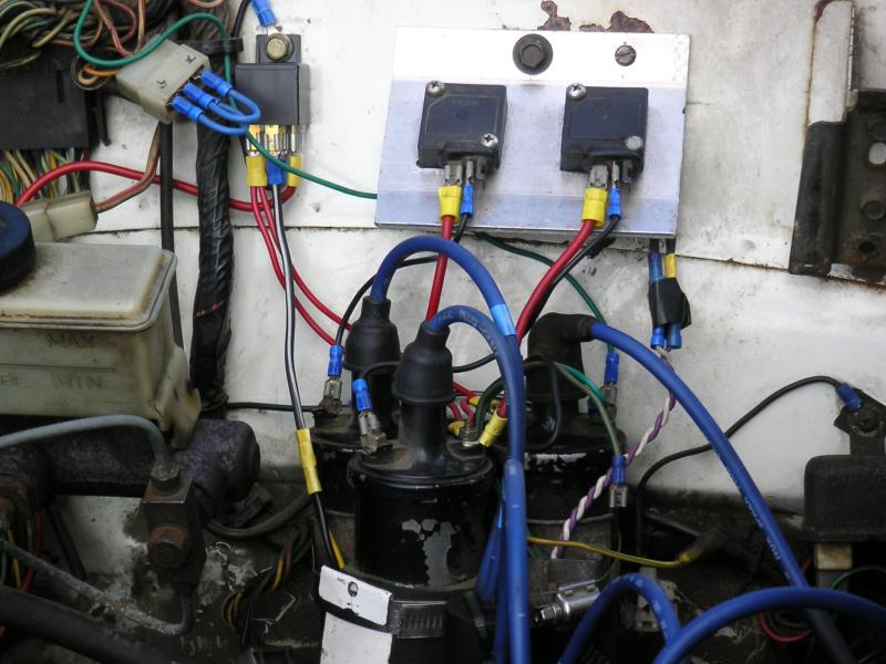
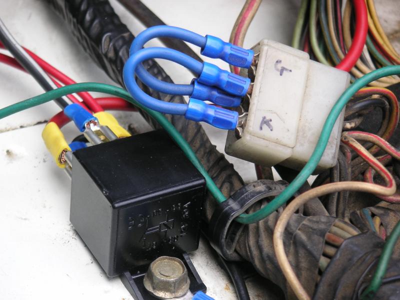
A closeup showing the relay and the jumpered terminals of the external voltage regulator's connector. You can do something like this in a '79 RX-7 if you want. G = gen/alt light in dash. K = ignition key switch in the ON position. They are then connected to the wires in the harness that runs over to the engine. You'll need to determine which wires do what on your vehicle before attempting a swap like this.
I tried a new wiring technique to supply 12V to the coils. I used thinner wires, but they're doubled-up so it acts like a single, thicker wire, yet it's more convenient to deal with/build since the wires are thinner. You can see the two thinner wires coming from a single quick disconnect terminal on the relay in the other pictures above. If I use this technique in the future, I'll probably go one or two sizes thicker in guage just to be on the safe side.
No need to kill a pickup by cutting off its connector or gutting an ignitor. As you can see, I filed down a couple male quick disconnects and test fitted them untill they were snug and wouldn't fall out. They have never given the PO or me any problems since this truck got DLIDFIS a couple years ago.
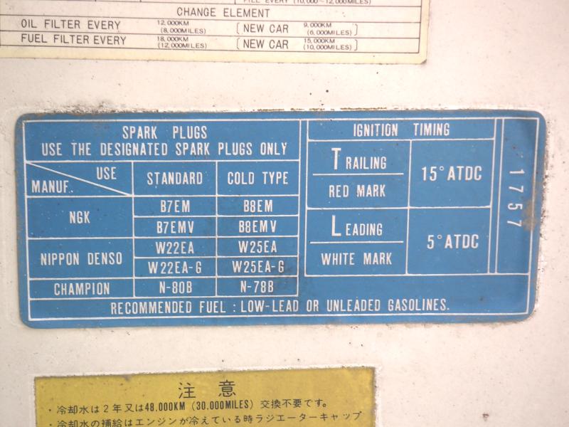
A few people have brought up the subject of B7EM plugs recently (including myself). The '74 REPU is just one of the vehicles that came stock with them. Oh, notice the 10� LT split? I've still got a 10� split, but the leading timing is set to 0� TDC at idle without vacuum advance on an FB dizzy. No more points for me.
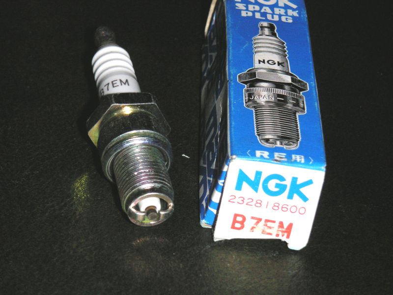
Speaking of B7EM, here's hoping you never need to use them. Check out that tiny gap!
Ignitor plate in my '76 CD Cosmo. There was very little room for the ignitors to be mounted near the coils. The voltage regulator (also removed) was way over on the firewall and thus too far away to look good. I like how the green and red wires turned out here.
My white REPU. It had an external voltage regulator at first so I had to move the aluminum plate over a little compared to my red REPU. I later swapped in an internally regualted alt so I could then remove the external reg. I installed a relay at one of the old voltage reg bolt holes just a couple days ago. The engine runs noticeably better now.
A closeup showing the relay and the jumpered terminals of the external voltage regulator's connector. You can do something like this in a '79 RX-7 if you want. G = gen/alt light in dash. K = ignition key switch in the ON position. They are then connected to the wires in the harness that runs over to the engine. You'll need to determine which wires do what on your vehicle before attempting a swap like this.
I tried a new wiring technique to supply 12V to the coils. I used thinner wires, but they're doubled-up so it acts like a single, thicker wire, yet it's more convenient to deal with/build since the wires are thinner. You can see the two thinner wires coming from a single quick disconnect terminal on the relay in the other pictures above. If I use this technique in the future, I'll probably go one or two sizes thicker in guage just to be on the safe side.
No need to kill a pickup by cutting off its connector or gutting an ignitor. As you can see, I filed down a couple male quick disconnects and test fitted them untill they were snug and wouldn't fall out. They have never given the PO or me any problems since this truck got DLIDFIS a couple years ago.
A few people have brought up the subject of B7EM plugs recently (including myself). The '74 REPU is just one of the vehicles that came stock with them. Oh, notice the 10� LT split? I've still got a 10� split, but the leading timing is set to 0� TDC at idle without vacuum advance on an FB dizzy. No more points for me.
Speaking of B7EM, here's hoping you never need to use them. Check out that tiny gap!
Ignitor plate in my '76 CD Cosmo. There was very little room for the ignitors to be mounted near the coils. The voltage regulator (also removed) was way over on the firewall and thus too far away to look good. I like how the green and red wires turned out here.
09-03-04, 03:55 PM
#56
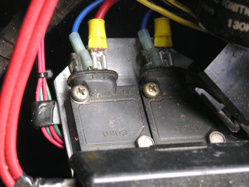
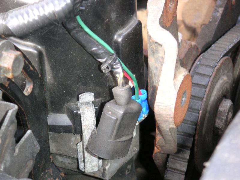
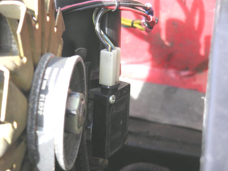
Again, you can see the quick disconnects were filed down and fitted snugly to the pickup plug. They've never given me trouble over the last couple years since I installed DLIDFIS. The AC bracket was designed with a points dizzy in mind, so there is actually not enough room for an ignitor there. Hehe.
The coils' position is left over from when this car had SLIDFIS, so in order to hook up DLIDFIS, I just routed new wires to them from the ignitor plate. If I had to do it over again, I would rotate the coils into a better position. This car also still needs a relay.
The red REPU was my first dead/gutted ignitor experiment. It's a J-105. Since it's only used as an electrical pickup signal transfer device (heh, that's a complicated way to say it), it only needs one screw. There is no clip on the T shaped connector, but it doesn't feel like it'll fall off so I'm ok with it.
I used speaker wire and other odds and ends because I didn't have anything else at the time (it was the poor man's ignition system afterall). I'll probably redo it with 10AWG and better connectors eventually. This was also my first use of a relay with DLIDFIS. The stock ignition wires were so bad that they lost a volt when compared to the alt's output. The wires at the ignition switch itself would actually get rather hot to the touch. Adding a relay with a feed wire from the starter solenoid's thick battery wire solved that little problem, as well as an annoying blip at idle.
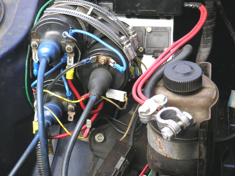
Here is my MG's DLIDFIS. I like how it turned out. Again, you can see the red wire in T shaped connector on the gutted ignitor. Red goes over to the red wires and connectors and the black wire goes to the green wires and connectors on the ignitors. Idiot proof.
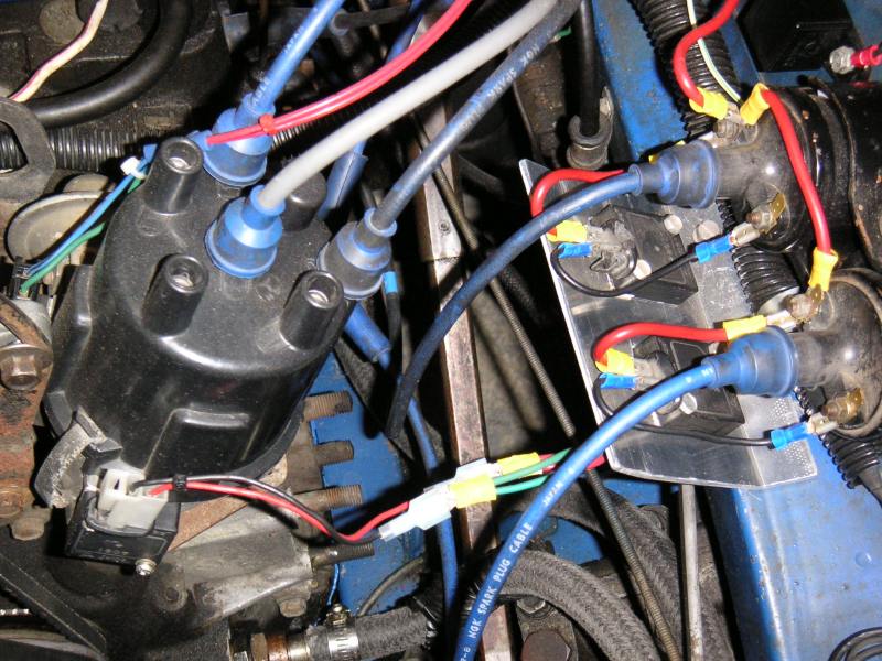
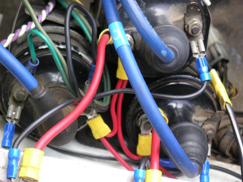
A red 10AWG wire comes directly from the battery, to the relay, the ignition switch (thin white wire) turns the relay on and off. The other side of the relay has a 10AWG wire which Ys apart to the trailing coil in the stock location (lower right of pic; it's a Hanshin coil), and over to the leading coils (Diamond, IIRC). It jumps from one leading coil to the other. Each leading ignitor has a 10awg power wire (+ or B) and a thinner trigger wire (- or C).e. The tach signal wire is green (on trailing coil). The other two red wires go over to the trailing ignitor. They're kinda thin and very stiff and I'd like to make a new harness with a thicker wire someday. The little black wire in the bottom middle of the picture with the red ring terminal is the relay's ground wire (incase you didn't know). I really need to get a new set of plug wires. At least these don't seem to leak.
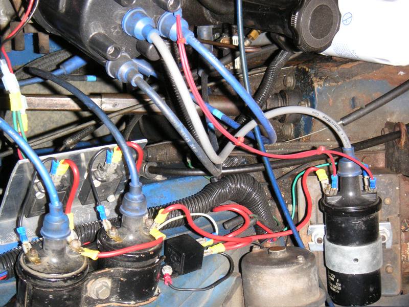
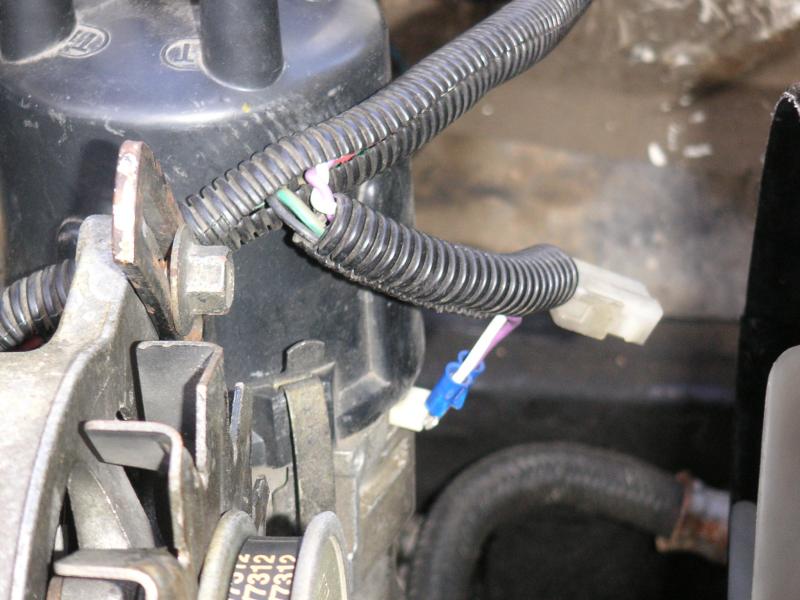
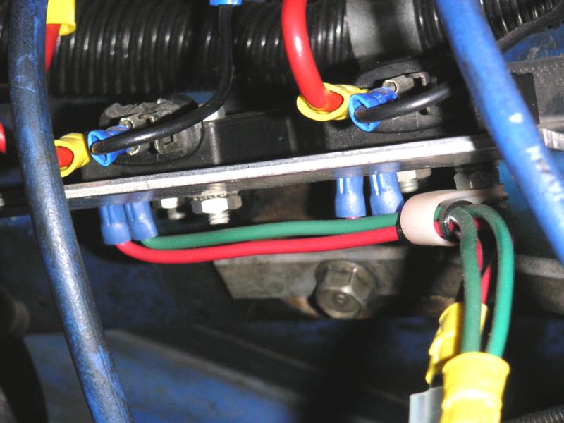
Here's a closeup of the pickup signal wires. Heh, what's a Mazda bolt doing down there? It's not on the engine.
The coils' position is left over from when this car had SLIDFIS, so in order to hook up DLIDFIS, I just routed new wires to them from the ignitor plate. If I had to do it over again, I would rotate the coils into a better position. This car also still needs a relay.
The red REPU was my first dead/gutted ignitor experiment. It's a J-105. Since it's only used as an electrical pickup signal transfer device (heh, that's a complicated way to say it), it only needs one screw. There is no clip on the T shaped connector, but it doesn't feel like it'll fall off so I'm ok with it.
I used speaker wire and other odds and ends because I didn't have anything else at the time (it was the poor man's ignition system afterall). I'll probably redo it with 10AWG and better connectors eventually. This was also my first use of a relay with DLIDFIS. The stock ignition wires were so bad that they lost a volt when compared to the alt's output. The wires at the ignition switch itself would actually get rather hot to the touch. Adding a relay with a feed wire from the starter solenoid's thick battery wire solved that little problem, as well as an annoying blip at idle.
Here is my MG's DLIDFIS. I like how it turned out. Again, you can see the red wire in T shaped connector on the gutted ignitor. Red goes over to the red wires and connectors and the black wire goes to the green wires and connectors on the ignitors. Idiot proof.
A red 10AWG wire comes directly from the battery, to the relay, the ignition switch (thin white wire) turns the relay on and off. The other side of the relay has a 10AWG wire which Ys apart to the trailing coil in the stock location (lower right of pic; it's a Hanshin coil), and over to the leading coils (Diamond, IIRC). It jumps from one leading coil to the other. Each leading ignitor has a 10awg power wire (+ or B) and a thinner trigger wire (- or C).e. The tach signal wire is green (on trailing coil). The other two red wires go over to the trailing ignitor. They're kinda thin and very stiff and I'd like to make a new harness with a thicker wire someday. The little black wire in the bottom middle of the picture with the red ring terminal is the relay's ground wire (incase you didn't know). I really need to get a new set of plug wires. At least these don't seem to leak.
Here's a closeup of the pickup signal wires. Heh, what's a Mazda bolt doing down there? It's not on the engine.
09-04-04, 02:18 PM
#59
[QUOTE=Jeff20B]
Here is my gutted ignitor with color coded wires soldered to the pins. Notice how the pins are jumpered. This allows the red and green wires to stay in the same positions; green is on the right-hand pin when viewed from the back. In other words, when the gutted ignitor is installed, the red wire will be on the right-hand side of the T shaped connector at the top of the ignitor. Red=Right. This is my prefered wiring method and is very easy to remember IF you jumper the pins as I have done.
QUOTE]
By soldering wires as indicated above, the top right becomes positive while the other, top left, becomes negative. Originally, left is positive while right is negative. So the polarity is reversed. The only problem I have is troubleshooting. No disrespect but If I am to troubleshoot your install, I may need to take it apart and re-wire it if I cant figure it out. As a HVACR service tech/installer, I prefer to do it based on the schematic. Change in color is normal but keep it consistent. This will elminate lots of swearing and frustration. Who knows, the next person in line could be me. Try working on an ice machines which consist of spaghetti wires and multiple sensors. Its a total PITA.
09-04-04, 03:25 PM
#60
Your point is valid and I do respect it. However...
The ignitor is now gutted, so B and C are moot. This was the logic I used several years ago when I gutted my first dead ignitor, and it has never caused any problems during troubleshooting (like recently on my GLC, which is a whole 'nother thread) or at any other time in the past. Besides, the little S and G raised letters can be viewed just as easily as the B and C letters, and their polarity is simply translocated to the top of the ignitor. C=minus(-)=S and B=plus(+)=G. In other word, C=- and B=+. Super simple. I'd prefer not to have to flip them around.
As for having to take it apart to determine anything/troubleshoot, if you weren't familier with the S and G terminals' function/color, the deepest you'd need to dig on any of my setups would be to take off the dizzy cap, rotor, and the little aluminum cover and observe the colored pickup wires' location as they enter the back of the ignitor (it just take a couple seconds). Logically, it made more sense to keep the wires in the same positions from when they enter the ignitor to when they exit it, with respect to the and red and green wires' position in the pickup plug. I considered your approach to wiring the jumper wires at first so they wouldn't have to cross one over the other internally, but again, since B and C are no longer connected to a coil as they were when the ignitor was stock, it didn't make a whole lot of sense to keep adhering to the no-longer-valid B and C markings.
If the red pickup wire really is positive, why must it be grounded when hooking up a pickup to an FC ignitor? It's not a good idea try this as the green wire can't supply a decent square wave signal, but that's for another thread.
Why do the markings show S (signal) to be negative while G (ground) is positive? Positive ground? Pretty weird alright.
For that matter, how can you explain why the MSD's purple wire goes to the pickup's green wire while the MSD's green wire goes to the pickup's red wire? Of course it has to do with the MSD's mag trigger circuitry (negative pulse triggered, and all that), but it seems backwards to me as far as the colors they used.
Maybe worrying about how the wires are routed inside a gutted ignitor is an unproductive use of time and can be done any direction the gutter wants to do it? Perhaps somebody will see this thread and make the descision for him/herself without any further input from us?
In closing, I've just gotta say that I still think my way of wiring makes more sense from the pickup wires'/plug's perspective, which is what we're concerned with in gutting dead ignitors anyway. It's extremely simple to remember the polarity by looking at the S and G markings on the front of the ignitor, or if necessary, taking off the cap, rotor and metal cover to take a gander at the colored wires. If you're red-green colorblind, well, that's a whole 'nother thread.
Originally, left is positive while right is negative. So the polarity is reversed.
As for having to take it apart to determine anything/troubleshoot, if you weren't familier with the S and G terminals' function/color, the deepest you'd need to dig on any of my setups would be to take off the dizzy cap, rotor, and the little aluminum cover and observe the colored pickup wires' location as they enter the back of the ignitor (it just take a couple seconds). Logically, it made more sense to keep the wires in the same positions from when they enter the ignitor to when they exit it, with respect to the and red and green wires' position in the pickup plug. I considered your approach to wiring the jumper wires at first so they wouldn't have to cross one over the other internally, but again, since B and C are no longer connected to a coil as they were when the ignitor was stock, it didn't make a whole lot of sense to keep adhering to the no-longer-valid B and C markings.
If the red pickup wire really is positive, why must it be grounded when hooking up a pickup to an FC ignitor? It's not a good idea try this as the green wire can't supply a decent square wave signal, but that's for another thread.
Why do the markings show S (signal) to be negative while G (ground) is positive? Positive ground? Pretty weird alright.
For that matter, how can you explain why the MSD's purple wire goes to the pickup's green wire while the MSD's green wire goes to the pickup's red wire? Of course it has to do with the MSD's mag trigger circuitry (negative pulse triggered, and all that), but it seems backwards to me as far as the colors they used.
Maybe worrying about how the wires are routed inside a gutted ignitor is an unproductive use of time and can be done any direction the gutter wants to do it? Perhaps somebody will see this thread and make the descision for him/herself without any further input from us?
In closing, I've just gotta say that I still think my way of wiring makes more sense from the pickup wires'/plug's perspective, which is what we're concerned with in gutting dead ignitors anyway. It's extremely simple to remember the polarity by looking at the S and G markings on the front of the ignitor, or if necessary, taking off the cap, rotor and metal cover to take a gander at the colored wires. If you're red-green colorblind, well, that's a whole 'nother thread.
 09-06-04, 02:43 AM
#62
wackoracer is going to set me up for DLFIDS b4 7stock... hopefully
question abounds me in such that how come people like danny, web777, disregarded using directfire once he went turbo on his GSL-SE. i'm just guessing that @ higher RPM, he'll pretty much be playing w/ detonation since the spark is too strong.... ??
question abounds me in such that how come people like danny, web777, disregarded using directfire once he went turbo on his GSL-SE. i'm just guessing that @ higher RPM, he'll pretty much be playing w/ detonation since the spark is too strong.... ??
 09-06-04, 04:25 AM
#65
Adolf Hitler Verfechter
Join Date: Sep 2002
Location: Northern South Africa
Posts: 969
Likes: 0
Received 0 Likes
on
0 Posts
This is the best ignition thread ever!
I think i have my + and - switched on my pickups in the Dizzy.
That might explain why i had a jumpy tach signal the weekend.
I think i have my + and - switched on my pickups in the Dizzy.
That might explain why i had a jumpy tach signal the weekend.
09-06-04, 04:26 AM
#66
Maybe his ECU didn't support ignition? Maybe he felt that keeping the stock dizzy would mean less to go wrong? Sometimes people do different things for different reasons. All I can do is recommend direct fire and state reasons why it's great to use over the alternatives out there.
A strong spark won't cause detonation. It sounds like proper tuning is something he ought to look into first. Besides, what about all those T2s with direct fire? It's not as if forced induction automatically requires the removal of the late leading spark.
Let him know that the RX-7 club knows about him.
Last edited by Jeff20B; 09-06-04 at 04:29 AM.
09-06-04, 12:55 PM
#68
Originally Posted by Jeff20B
Maybe his ECU didn't support ignition? Maybe he felt that keeping the stock dizzy would mean less to go wrong? Sometimes people do different things for different reasons. All I can do is recommend direct fire and state reasons why it's great to use over the alternatives out there.
A strong spark won't cause detonation. It sounds like proper tuning is something he ought to look into first. Besides, what about all those T2s with direct fire? It's not as if forced induction automatically requires the removal of the late leading spark.
Let him know that the RX-7 club knows about him.
A strong spark won't cause detonation. It sounds like proper tuning is something he ought to look into first. Besides, what about all those T2s with direct fire? It's not as if forced induction automatically requires the removal of the late leading spark.
Let him know that the RX-7 club knows about him.

he bought the cartech turbo kit for GSL-SE.. correct me if i'm wrong web777
and yes, that's what i'm also thinking about, T2's w/ direct fire as well.
09-06-04, 03:11 PM
#69
Right near Malloy
iTrader: (28)
Join Date: Dec 1999
Location: Behind a workbench, repairing FC Electronics.
Posts: 7,835
Received 502 Likes
on
340 Posts
Supply and cost aside, is there any benefit to using GM HEI ignitors or Mopar ignitors over the J109's?
Say you had a box full of known good J109's, another box full of GM HEI Ignitors from the 1979 Nova, and another box full of those Mopars... Which would you use? Why?
Is one more reliable than the other?
Are all GM HEI ignitors the same, I recall someone got some from a vette, another complained about having to replace them on his van...
09-06-04, 04:37 PM
#70
Some have complained that the Mopar ignition modules (according to peejay they are not true ignitors) tend to fail every few years. They last about 10 years each in my dad's '82 Ram van that he got in '86 with nearly 100k on it. It now has over 200k on the chassis and a rebuilt engine and is on it 3rd ignition module. He recently replaced it when troubleshooting. The problem turned out to be something else so I have it to experiement with. peejay said people try to ground the modules to rust sometimes which could lead to at least some of the failures. The funky 5 or 4 wire connector usually needs to be sourced from a wrecking yard. They are also rather large (half the size of an MSD box).
The GM HEI ignitors are compact and use easily found quick disconnect terminals. They produce more heat than a J-109 so an adequate heat sink with heat sink compound must be used. They can also be purchased new for only $15.99 and up at any auto parts store.
I'm not too familier with the reliability issues with HEI ignitors, but GM used them in all or most of their vehicles for at least a decade. Then again, every auto parts store sells them... At least they're cheap and easy to find.
I would guess that the HEI ignitors vary between aftermarket manufaturers. They're all supposed to work the same though. I don't know if one brand name is better than another. I installed the expensive Nascar brand because that's what the owner wanted. I'd personally go with the $15.99 ones on my projects.
The supply of cheap used J-109s will dry up some day. New, they're like um $200 or something at the dealer. Since several of my DLIDFIS installs are based on the J-109s, I'm going to need to worry about keeping a few spares handy. The small tweeter quick disconnects are usually more difficult to find than the more common sizes on the HEI ignitors, if that's important to anyone.
I think most of use will have a basic idea of how long J-109s last. I've gutted a few dead ones, if that's any indication. I have no idea how many miles they had one them.
I think I would choose the GM HEI ignitors over the others if I had three boxes sitting in front of me. The simple reason is that they are more plentiful, cheaper, easier to find simple quick disconnect connectors for, and the best reason is that if your starter has enough cranking speed to crank the engine, it'll be enough to trigger the HEI ignitors to spark the coils (my friend's B2000 had a dead battery with slow cranking starter that was still able to start the engine with nothing but GM HEIs for ignitors). Bench testing showed that the dizzy needed to be spun by hand a little bit faster than with a single J-109, but again, real world testing has shown that this is not a problem. I've installed GM HEI ignitors on two vehicles so far, and will most likely continue using them. I'll hang on to the few J-109s I still have for my exisiting DLIDFIS installs as spares.
Last edited by Jeff20B; 09-06-04 at 04:42 PM.
09-06-04, 05:01 PM
#71
Right near Malloy
iTrader: (28)
Join Date: Dec 1999
Location: Behind a workbench, repairing FC Electronics.
Posts: 7,835
Received 502 Likes
on
340 Posts
Excellent. Thanks.
Now, How crucial is length of wire from the mag pickup to the ignitor? How crucial is shielding?
I see the three ignitors on your REPU as mounted on the fender. Has this worked well, or would it be a better idea to mount the ignitors on the engine near the dizzy, then run wire to the coils?
Now, How crucial is length of wire from the mag pickup to the ignitor? How crucial is shielding?
I see the three ignitors on your REPU as mounted on the fender. Has this worked well, or would it be a better idea to mount the ignitors on the engine near the dizzy, then run wire to the coils?
Last edited by Pele; 09-06-04 at 05:05 PM.
09-07-04, 02:06 AM
#72
I think the longest pickup wires I've ever ran are probably up to 2 feet. It never had a problem with false triggers. I've never used shielded wire. I need to update my DLIDFIS article to mention this.
Three ignitors on my REPU? Which picture are you refering to?
Mount the ignitors and coils wherever it's convenient for you. This philosophy has always worked for me regardless of wire length and component location.
Three ignitors on my REPU? Which picture are you refering to?
Mount the ignitors and coils wherever it's convenient for you. This philosophy has always worked for me regardless of wire length and component location.
 09-07-04, 07:10 AM
#75
Right near Malloy
iTrader: (28)
Join Date: Dec 1999
Location: Behind a workbench, repairing FC Electronics.
Posts: 7,835
Received 502 Likes
on
340 Posts
Originally Posted by Jeff20B
I think the longest pickup wires I've ever ran are probably up to 2 feet. It never had a problem with false triggers. I've never used shielded wire. I need to update my DLIDFIS article to mention this.
Three ignitors on my REPU? Which picture are you refering to?
Mount the ignitors and coils wherever it's convenient for you. This philosophy has always worked for me regardless of wire length and component location.
Three ignitors on my REPU? Which picture are you refering to?
Mount the ignitors and coils wherever it's convenient for you. This philosophy has always worked for me regardless of wire length and component location.
I may not need to source a dead ignitor, as I see it, it adds one more point to have a bad connection caused by moisture and corrosion... Between the pickup and dead ignitor, then from the dead ignitor to the wiring... Might as well elimiate it and just hook wiring straight to the mag pickups.