(IGNITION) 2GCDFIS diagram. Is this correct?
 01-10-06, 05:49 PM
#1
WWW.SUPERCHARGED-RX7.COM
Thread Starter
(IGNITION) 2GCDFIS diagram. Is this correct?
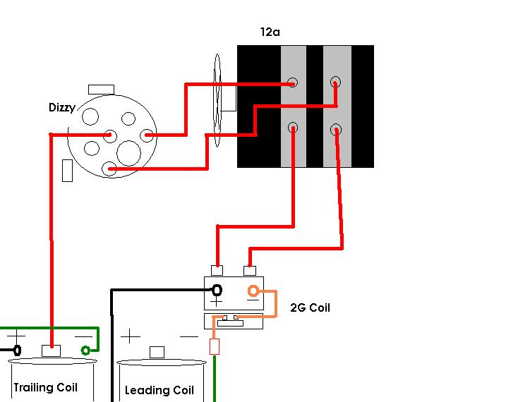
Here's a diagram of how I think it should all be hooked up as. Is this correct? Sorry about the crappy generic paint work, but it makes its point.
All the write ups and pics are great, but I love diagrams.
Should I leave the 2g igniter and wires intact for when the TT becomes available?. Can't wait.
Thanks
All the write ups and pics are great, but I love diagrams.
Should I leave the 2g igniter and wires intact for when the TT becomes available?. Can't wait.
Thanks
 01-10-06, 09:47 PM
#2
---
Join Date: Sep 2005
Location: Minneapolis, MN
Posts: 568
Likes: 0
Received 0 Likes
on
0 Posts
yeah it looks correct. and you cant really leave the wires intact, as you have to cut them off the ignitor. keep the ignitor though and you can solder new wires to it if/when you get the TT setup.
01-10-06, 11:05 PM
#4
WWW.SUPERCHARGED-RX7.COM
Thread Starter
Hmm? What if I wanted to hook up a MSD 6a to the 2GCDF and eliminate the stock igniter? Could I do it like it shows here on my diagram? If so, do I just remove the stock igniter and use the wires that where attached to it?
Sorry if this has been asked before. I did do alot of searches and there's just tons of ways that people are doing it and it's kind of confusing.
Sorry if this has been asked before. I did do alot of searches and there's just tons of ways that people are doing it and it's kind of confusing.
01-10-06, 11:55 PM
#5
Actually, you don't have to cut the wires for the regular 2GCDFIS. You only need to remove one of the wires from either the + or - post. It depends because Mazda used two different ways of wiring the balast resistor. I can write something later today to show. That way you can use the TT later. I currently have the TT kits for sale. They will be listed for about 1 month. I will list the assembled ones probably today sometime.
http://www.rotaryx.com/index.php?a=1002&b=249
http://www.rotaryx.com/index.php?a=1002&b=249
01-11-06, 07:02 AM
#6
Originally Posted by Kim's FB
Hmm? What if I wanted to hook up a MSD 6a to the 2GCDF and eliminate the stock igniter? Could I do it like it shows here on my diagram? If so, do I just remove the stock igniter and use the wires that where attached to it?
Sorry if this has been asked before. I did do alot of searches and there's just tons of ways that people are doing it and it's kind of confusing.
Sorry if this has been asked before. I did do alot of searches and there's just tons of ways that people are doing it and it's kind of confusing.
msd 6a/6al to FC coil is easy. ALL YOU NEED IS THE COIL AND BE SURE TO CUT ALL WIRES FROM COIL TO IGNITER; OR YOU WILL BURN THE MSD BOX. Well, keep the igniter too due to the moutning bracket. Just connect the MSD's thin orange and black wires to the coill.
01-11-06, 07:48 AM
#7
Waffles - hmmm good
iTrader: (1)
I second the "don't cut the wires" approach. You never know when you might need to switch them around. This also goes for the existing wiring harness leads to the stock ignition. Keep them intact so you can always go back to stock in an emergency (like, say your 2G coil fails for instance). With no tools or just a screw driver you should be able to get the stock ignition wired back up and running in a pinch. You''l thank yourself later.
Trending Topics
01-11-06, 08:49 AM
#8
---
Join Date: Sep 2005
Location: Minneapolis, MN
Posts: 568
Likes: 0
Received 0 Likes
on
0 Posts
Originally Posted by t_g_farrell
I second the "don't cut the wires" approach. You never know when you might need to switch them around. This also goes for the existing wiring harness leads to the stock ignition. Keep them intact so you can always go back to stock in an emergency (like, say your 2G coil fails for instance). With no tools or just a screw driver you should be able to get the stock ignition wired back up and running in a pinch. You''l thank yourself later.
GSL-SE addict would probably know better than me. I guess I didnt think of it that way...
Hey Kim's FB, do you mind if I put your diagram in my writeup? Might help lessen the confusion.
01-11-06, 02:19 PM
#9
How to: 2GCDFIS without removing 2nd gen ignitor
Okay, guys. Here is how to do the regular 2GCDFIS without removing the 2nd gen ignitor. I recommend doing it this way so you can:
1. upgrade to TT later
2. be able to resell the 2nd gen coil if you sell car, go back to stock, etc.
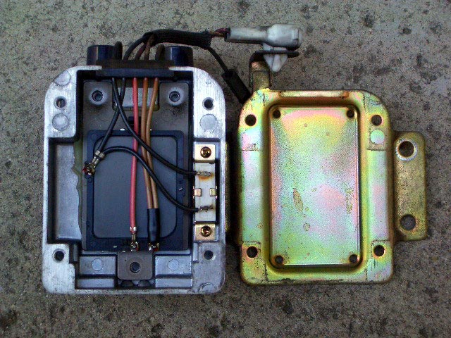
First, you will need to remove the four screws from the back of the coil pack to take off the back cover. You will need to inspect how the balast resistor is wired into the circuit. Mazda wired it on the - side of the coil on some years and on the + side during other years. It does not matter which side the resistor is on. It just needs to be in the circuit to limit the current load on the J-109.
1. If the resistor is on the + side:
In this case, the resistor is wired on the + side of the circuit. You will notice a tan wire comes in from the top of the coil, goes through the balast resistor, then goes to the coil +.
In this case:
1. remove the black wire from - terminal of coil
2. connect - terminal wire from the stock leading coil to the - on the 2nd gen coil
3. connect 12v switched to the tan wire coming out of the top of the coil. You may need to cut the white connector or find a mating end.
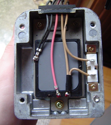
2. If the resistor is on the - side:
In this case, the resistor is wired on the - side of the circuit. You will notice a black wire comes in from the top of the coil, connects to 2nd gen ignitor, goes through the balast resistor, then goes to the coil -.
In this case:
1. remove the tan wire from + terminal of coil
2. connect 12v switched to coil +
or
1b. leave tan wire in place
2b. connect 12v switched to the tan wire that come out of the top of the coil
3. connect - terminal wire from the stock leading coil to the little black wire coming out of the top of the 2nd gen coil
Hope this makes sense. This will let you try the 2GCDFIS while making it easy to upgrade to TT or something else in the future.
Kent
1. upgrade to TT later
2. be able to resell the 2nd gen coil if you sell car, go back to stock, etc.
First, you will need to remove the four screws from the back of the coil pack to take off the back cover. You will need to inspect how the balast resistor is wired into the circuit. Mazda wired it on the - side of the coil on some years and on the + side during other years. It does not matter which side the resistor is on. It just needs to be in the circuit to limit the current load on the J-109.
1. If the resistor is on the + side:
In this case, the resistor is wired on the + side of the circuit. You will notice a tan wire comes in from the top of the coil, goes through the balast resistor, then goes to the coil +.
In this case:
1. remove the black wire from - terminal of coil
2. connect - terminal wire from the stock leading coil to the - on the 2nd gen coil
3. connect 12v switched to the tan wire coming out of the top of the coil. You may need to cut the white connector or find a mating end.
2. If the resistor is on the - side:
In this case, the resistor is wired on the - side of the circuit. You will notice a black wire comes in from the top of the coil, connects to 2nd gen ignitor, goes through the balast resistor, then goes to the coil -.
In this case:
1. remove the tan wire from + terminal of coil
2. connect 12v switched to coil +
or
1b. leave tan wire in place
2b. connect 12v switched to the tan wire that come out of the top of the coil
3. connect - terminal wire from the stock leading coil to the little black wire coming out of the top of the 2nd gen coil
Hope this makes sense. This will let you try the 2GCDFIS while making it easy to upgrade to TT or something else in the future.
Kent
01-11-06, 05:16 PM
#10
Blew my 3rd one 12/8/08
iTrader: (2)
Join Date: Jun 2003
Location: Inman SC
Posts: 821
Likes: 0
Received 0 Likes
on
0 Posts
well i've been running without the resistor ever since i did the normal 2GC.. haven't had a prob, actually my car wouldn't even crank with the resistor in line, so i didn't use it and have been fine.
01-11-06, 05:17 PM
#11
Dude, this is slated for instant archiving!
Kim's FB, did you make those diagrams? They're very clear, you rock. You should make a Transistor Trick Box one Though I don't know if there are different versions of the TT box that get wired differently.
Jon
Kim's FB, did you make those diagrams? They're very clear, you rock. You should make a Transistor Trick Box one
Though I don't know if there are different versions of the TT box that get wired differently.Jon
01-11-06, 06:41 PM
#12
WWW.SUPERCHARGED-RX7.COM
Thread Starter
Haha, talking about diagrams, I took gsl-se addict's instructions and made them into a diagram.
Please feel free to take those diagrams and use! But first let's make sure gsl-se addict looks them over first. I'm concerned about the igniter being connected. Would it matter? Or should those wires be cut from the igniter?
Thanks everyone!
Please feel free to take those diagrams and use! But first let's make sure gsl-se addict looks them over first. I'm concerned about the igniter being connected. Would it matter? Or should those wires be cut from the igniter?
Thanks everyone!
01-17-06, 08:14 PM
#13
WWW.SUPERCHARGED-RX7.COM
Thread Starter
Ok, so I got my 2nd gen coil today and will install it this weekend.
On my coil the resistor is on the negative side, can someone (cough, cough, gsl-se addict) confirm that my diagrams are correct?
Thanks!!
On my coil the resistor is on the negative side, can someone (cough, cough, gsl-se addict) confirm that my diagrams are correct?
Thanks!!
 You don't have to worry abot the wires still connected to the ignitor. The tan one just provides power to the ignitor. The black one justs "floats" and then the ignitor pulls to ground when firing.
01-22-06, 07:50 PM
You don't have to worry abot the wires still connected to the ignitor. The tan one just provides power to the ignitor. The black one justs "floats" and then the ignitor pulls to ground when firing.
01-22-06, 07:50 PM
#15
Junior Member
Join Date: Aug 2004
Location: fl
Posts: 17
Likes: 0
Received 0 Likes
on
0 Posts
Has anybody noticed what is critically wrong with the paint diagrams at the start of this post. If you followed them exactly you car will run like @%#*.
The plug wires are shown going to the wrong rotors, L1 wire is going to the L2 spark plug, T1 wire is going to the T2 spark plug and so on.
Yes your car will still start and you can ever rev the engine just sitting there, you can even drive it ever so gingerly, but as soon as you try to give it even moderate throttle under load, you get some nasty pre-ignition, (because you are 60 degrees out of sync) sounds like it is trying to throw a rod (I know we do not have connecting rods).
Why do we know this because we wired it up like the drawing and found out. When correctly wired, it runs great (except the backfire that we liked so much is now gone)
01-22-06, 11:26 PM
#16
WWW.SUPERCHARGED-RX7.COM
Thread Starter
Hmm, didn't notice that. The diagram was to show how to hook up the 2nd gen coil, that's why no thought was put into what plug goes where on the trailing side. I will fix the trailing plug wires part. As for the leading, it does not matter.
So no one gets confused, T1 and T2 gets moved to L1 and L2 on the dizzy along with the plug wire from the Trailing coil. That one gets moved to where the leading one was originally on the distributor cap.
Thanks for pointing that out.
On a side note, I did the install and my RX-7 today and it's great. Check out my clean wiring.

Thread
Thread Starter
Forum
Replies
Last Post

