(FUEL) How To: Repair a fuel level sender
 09-14-08, 10:54 PM
#1
(FUEL) How To: Repair a fuel level sender
Electrical failure of the tank sender on an SA is a problem, because replacement units are no longer available, because useable salvage units are becoming very hard to find, and will most likely be very worn anyway due to their age.
Tanks senders from later models will fit in the hole, but there are a couple of issues with using them:
1) Because the 81-on gas tanks were deeper, the sender will not read properly across the full range, because the arm is too long. Getting a correct reading means modifying the float arm, which is "swaged" (the arm wire is crushed in place). Getting it calibrated just right could be tricky.
2) The electrical connection is different on the 84-85 senders; the SA sender has a two-pole connection, and the later models have a 3-pole to accomodate the "low fuel" sensor. This means modification of the wiring harness, and scrounging the right connecor, is required.
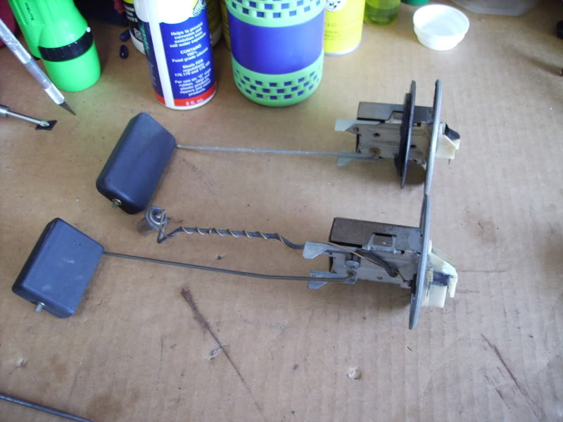
In the below pic, you can see an 85 sender compared to the unit out of my SA (85 on bottom, 80 on top)
The good news is, with a little care and caution, the most-common failure point for an SA tank sender (broken wire in the electrical resistor element, due to physical wear) can be repaired using electrical components removed from a new or used (if good) sender from either 81-83 or 84-85 model cars.
My sender suffered the eventual fate of all these tank senders; after a few gazillion trips up and down with the float arm, the "wiper" (the electrical contact that moves with the float) Wore through the wound wire "resistor" (the stationary part) to the point that it literally broke.
Depending on where the break is, the symptom for this could be a gauge that works correctly for only PART of a tankful (if broken near the bottom or middle) or never works at all (if broken near the top.)
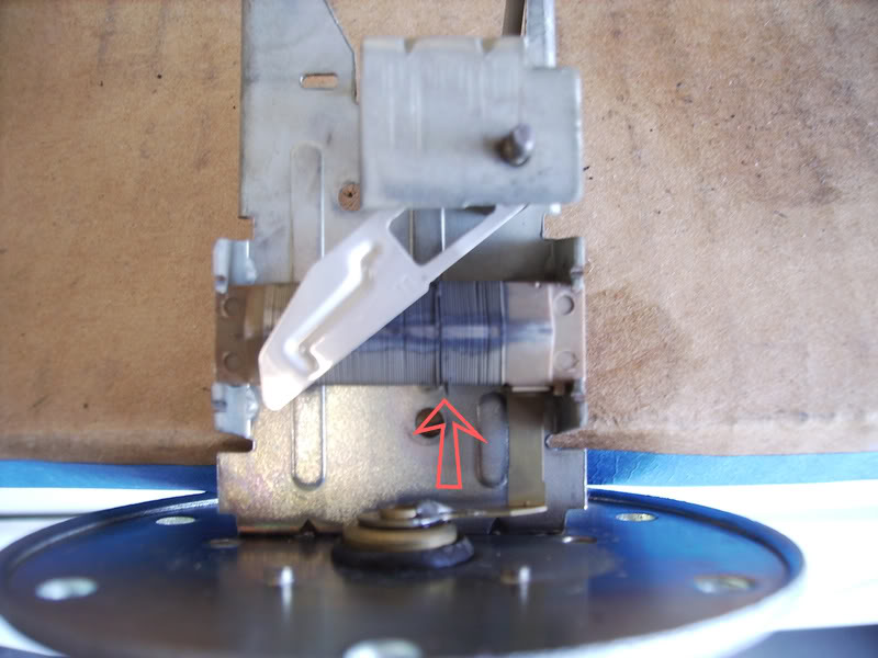
Here's how that failure looked after removing the sender from the tank, and taking the cover off by bending the little metal tab that holds it on. You can see the gap where the wire has broken, where the arrow is.
The wire elements in all first-gen senders are electrically the same, and are also physically the same size and shape, so a resistor element from a good-but-wrong-year sender will work fine in an SA sender. The trick is in swapping them without breakage, & re-securing the element.
First step (after removing the tin cover) is to, with the open side facing you, tie the float arm to the left-hand (full) end-stop. Notice that the wiper is now near the right-most end of the element, and you can now reach the Philips screw that holds the wiper to the float shaft, from the left side. Carefully loosen the screw and rotate the wiper clockwise, so that it no longer is on top of the element.
The resistor element is held in by two connections.
1) The copper contact from the element is soldered to the rivet in the middle of the baseplate; this forms the electrical connection from the element. Using a solder gun (100 watt or better) this can be de-soldered easily enough, just heat it and lift gently with a screwdriver. Don't overheat it; you don't want to melt the insulating seal that goes thru the base plate. It's not rivetted in place, so as soon as the solder is melted, it will slide up and off the contact with a light pry from a screwdriver.
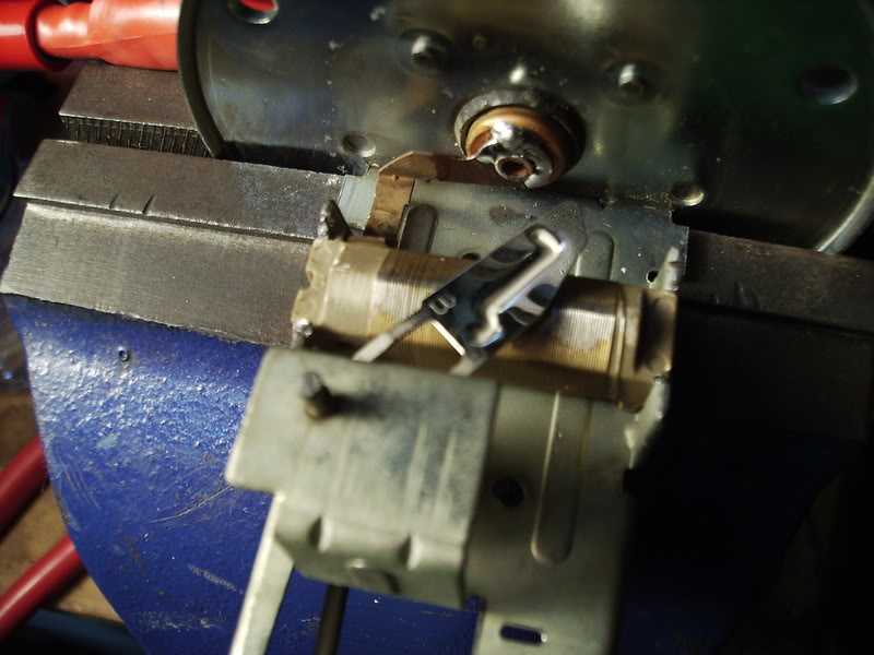
2) Hard part #1: the element is physically restrained by having been swaged into it's sheetmetal holder; looking closely at either end, you can see small tabs of the sheetmetal frame that have been bent over the element, to lock it on place.
The easiest way to get your "good" element out of the "donor" sender is to cut those little tabs off, and gently flex the metal restraining fingers away from the element. It's in there tightly, so work carefully; you don't want to abrade the element smaller.
Getting the "bad" element out of your SA sender is tricker, since you can't just cut it free - - you need to preserve the fingers and the tabs to hold the replacement element.
On mine, I ended up using pliers to squeeze the little tabs in, and then slightly flexed the fingers to get the element out.
The replacement element goes in right where the old one was removed from. There's an alignment pin on the back; Use this to make sure the new element is properly placed, then carefully bend & squeeze the sheetmetal back into place around the element. Fuel-proof epoxy would probably be a good option, so long as care is taken to keep it out of the way, but I didn't have any, so I ended up fiddling with vice, vicegrips, and sharp objects until I had the element firmly wedged back into position.
Solder the connection from the element back onto the contact rivet (use ROSIN core solder - - it's electrical!); make sure the solder "wets" the center contact properly, or it may fracture later.
Rotate the wiper back to the original position (right side of the element) and secure the philips screw). You can use an ohmmeter to test if the wiper is at the appropriate minimum resistance reading per the FSM, but be aware that the reading will not be accurate until you tighten the Phillips screw; the screw is part of the circuit path, and if it's loose it will shift the reading several ohms.
Untie the float arm, and swing it thru the range of motion, testing the resistance with the ohmmeter as specified by in the FSM.
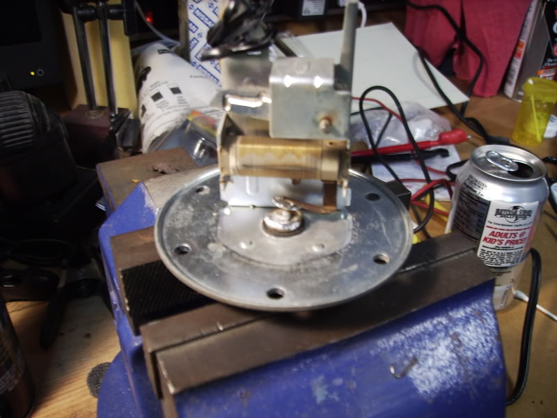
When done, it should look like this:
Put the tin cover back on & lock it in place with the tab, and your sender is ready to install.
Thanks to Jeff20B, Trochoid, 7uall, and gsl-se addict, and everyone else who participated in the "tank sender interchange" thread; they got me on the right path.
-DD
Tanks senders from later models will fit in the hole, but there are a couple of issues with using them:
1) Because the 81-on gas tanks were deeper, the sender will not read properly across the full range, because the arm is too long. Getting a correct reading means modifying the float arm, which is "swaged" (the arm wire is crushed in place). Getting it calibrated just right could be tricky.
2) The electrical connection is different on the 84-85 senders; the SA sender has a two-pole connection, and the later models have a 3-pole to accomodate the "low fuel" sensor. This means modification of the wiring harness, and scrounging the right connecor, is required.
In the below pic, you can see an 85 sender compared to the unit out of my SA (85 on bottom, 80 on top)
The good news is, with a little care and caution, the most-common failure point for an SA tank sender (broken wire in the electrical resistor element, due to physical wear) can be repaired using electrical components removed from a new or used (if good) sender from either 81-83 or 84-85 model cars.
My sender suffered the eventual fate of all these tank senders; after a few gazillion trips up and down with the float arm, the "wiper" (the electrical contact that moves with the float) Wore through the wound wire "resistor" (the stationary part) to the point that it literally broke.
Depending on where the break is, the symptom for this could be a gauge that works correctly for only PART of a tankful (if broken near the bottom or middle) or never works at all (if broken near the top.)
Here's how that failure looked after removing the sender from the tank, and taking the cover off by bending the little metal tab that holds it on. You can see the gap where the wire has broken, where the arrow is.
The wire elements in all first-gen senders are electrically the same, and are also physically the same size and shape, so a resistor element from a good-but-wrong-year sender will work fine in an SA sender. The trick is in swapping them without breakage, & re-securing the element.
First step (after removing the tin cover) is to, with the open side facing you, tie the float arm to the left-hand (full) end-stop. Notice that the wiper is now near the right-most end of the element, and you can now reach the Philips screw that holds the wiper to the float shaft, from the left side. Carefully loosen the screw and rotate the wiper clockwise, so that it no longer is on top of the element.
The resistor element is held in by two connections.
1) The copper contact from the element is soldered to the rivet in the middle of the baseplate; this forms the electrical connection from the element. Using a solder gun (100 watt or better) this can be de-soldered easily enough, just heat it and lift gently with a screwdriver. Don't overheat it; you don't want to melt the insulating seal that goes thru the base plate. It's not rivetted in place, so as soon as the solder is melted, it will slide up and off the contact with a light pry from a screwdriver.
2) Hard part #1: the element is physically restrained by having been swaged into it's sheetmetal holder; looking closely at either end, you can see small tabs of the sheetmetal frame that have been bent over the element, to lock it on place.
The easiest way to get your "good" element out of the "donor" sender is to cut those little tabs off, and gently flex the metal restraining fingers away from the element. It's in there tightly, so work carefully; you don't want to abrade the element smaller.
Getting the "bad" element out of your SA sender is tricker, since you can't just cut it free - - you need to preserve the fingers and the tabs to hold the replacement element.
On mine, I ended up using pliers to squeeze the little tabs in, and then slightly flexed the fingers to get the element out.
The replacement element goes in right where the old one was removed from. There's an alignment pin on the back; Use this to make sure the new element is properly placed, then carefully bend & squeeze the sheetmetal back into place around the element. Fuel-proof epoxy would probably be a good option, so long as care is taken to keep it out of the way, but I didn't have any, so I ended up fiddling with vice, vicegrips, and sharp objects until I had the element firmly wedged back into position.
Solder the connection from the element back onto the contact rivet (use ROSIN core solder - - it's electrical!); make sure the solder "wets" the center contact properly, or it may fracture later.
Rotate the wiper back to the original position (right side of the element) and secure the philips screw). You can use an ohmmeter to test if the wiper is at the appropriate minimum resistance reading per the FSM, but be aware that the reading will not be accurate until you tighten the Phillips screw; the screw is part of the circuit path, and if it's loose it will shift the reading several ohms.
Untie the float arm, and swing it thru the range of motion, testing the resistance with the ohmmeter as specified by in the FSM.
When done, it should look like this:
Put the tin cover back on & lock it in place with the tab, and your sender is ready to install.
Thanks to Jeff20B, Trochoid, 7uall, and gsl-se addict, and everyone else who participated in the "tank sender interchange" thread; they got me on the right path.
-DD
Last edited by Glazedham42; 09-16-08 at 02:45 PM.


Thread
Thread Starter
Forum
Replies
Last Post
82streetracer
1st Generation Specific (1979-1985)
7
08-23-15 09:28 AM
Megasquirt timing map and EGt ?? what do you guys think
immanuel__7
Megasquirt Forum
3
08-22-15 09:34 PM